Continue to Site

Welcome to our site!

Electro Tech is an online community (with over 170,000 members) who enjoy talking about and building electronic circuits, projects and gadgets. To participate you need to register. Registration is free. Click here to register now.

  • Welcome to our site! Electro Tech is an online community (with over 170,000 members) who enjoy talking about and building electronic circuits, projects and gadgets. To participate you need to register. Registration is free. Click here to register now.

proper transistor circuit??

Status
Not open for further replies.
Now you have a reasonable circuit except the 300 ohm resistors limit the LED current too low.
 
Using the TINA simulation

300 ohm = 72.81ma
250 ohm = 86.4ma
200ohm = 106ma
I think these figures are in the ballpark as I am using 2 - 2n2222's for the darlington pair which I will be using a TIP120 instead.
Thanks
 
300 ohm = 72.81ma
250 ohm = 86.4ma
200ohm = 106ma
I think these figures are in the ballpark
No.
That much current is impossible from a supply of only 12V, with 7.6V worth of LEDs in series and the voltage drop of the darlington transistor.

Ohm's Law says that 72.81mA in 300 ohms requires a voltage of 21.8V.
86.4mA in 250 ohms requires a voltage of 21.6V.
106mA in 200 ohms requires a voltage of 21.2V.

But the max voltage at the emitter of the darlington is 10.05V, the LEDs have a total voltage of 7.6V then the resistor will have a max voltage across it of only 2.45V.

Then the current is 2.45V/300 ohms= 8.2mA.
2.45V/250 ohms= 9.8mA.
2.45V/200 ohms= 12.3mA.

The max allowed current in no-name-brand ordinary LEDs is about 30mA. Use no more than 25mA.
 
what spec are we looking at

to determine that we have a max of 10.05 at the emitter.
getting ready to order parts and contemplating uping the supply voltage for the LEDs say 18v (need to locate transformer and a voltage regulator for the 555 / 4029
Plan is to have one wall wart and 2 seperate circuits
 

Attachments

  • Capture2-20-2009-4.32.24 PM.jpg
    Capture2-20-2009-4.32.24 PM.jpg
    171 KB · Views: 123
a darlington was suggested

by audioguru seeing how it takes less current to turn on and with the leds connected to the emitter it can then make the leds fade from one olor to the next.
I myself am just taking the adive from audioguru seeing how my knowledge of transistors is really weak.
the orginal circuit is https://images.bit-tech.net/content_images/2002/08/rainbow_led/circuit.gif
I am wondering how one determines the max voltage available at the emitter??
In audiogurus last post he mentioned that it was only 10.05v
how is this determined?? from the spec sheet or ??
 
The darlington transistors are "followers" of the slow ramps caused by the 10k resistors feeding 100uF capacitors to ground. The LEDs slowly brighten and slowly dim.

How can we calculate the max voltage at the LEDs without knowing what is their current? The schematic should state their forward voltage.
 
I am wondering how one determines the max voltage available at the emitter??
In audiogurus last post he mentioned that it was only 10.05v
how is this determined?? from the spec sheet or ??
The TIP120 darlington datasheet shows that its base to emitter voltage loss is 1.25V when its collector current is 100mA (25mA for each of the 4 strings of LEDs).
The base current of the darlington is almost zero so the output high voltage of the CD4029 is close to 12V. The 10k resistor to the base of the darlington will cause an additional voltage loss of about 0.7V. So the max emitter voltage is 10.05V when the supply is 12.0V.

But now you say the supply voltage is 18V!!!!!
Then everything is changed.

Why do you have so many threads about the same simple circuit?????
 
now I am feeling stupid

but even more so if I don't ask the questions.
first thanks for your patience It sounds like it would be easier to stay at 12Vcc
we have 100ma for the load (the 4 led strings) the leds are white so we have 3.4 (voltage drop)x 2 = 6.8 to 7v drop
12Vcc - 7Rl = 5v at 100 ma???
still confused about the 1.25 volt drop (base to emitter)
I see where we lose .7 volts but that 1.25 ??
remember I am lost somewhat when it comes to math.
I understand ohms law but thats it.
I got lost again when you mentioned voltage loss across the 10k resistor is .7
I assume thats what you ment??
its that pesky 1.25volt loss that I am trying to compute.
as for the one other post on this project, I figured it as an update but will keep in same thread-sorry for the confusion.
thanks again for you expert advice.
getting ready to order parts but first I plan on breadboarding the led arrays and measuring the actual currents and voltages.
am using "floor sweepings) for LEDs ---lol
 
Your 1.25 volt loss across the darlingtons? That's because there are TWO transistors inside and you drop about 0.7V per transistor. It's in the datasheet.
This is so simple compared to that equalizer / spectrum analyzer you were building for the Scouts. Did you ever finish it?
When I was 11 I got one of those 200in-one kits from the shack. Learned a lot from it.
**broken link removed**
 
The TIP120 has two transistors. The first one has very low current so its base to emitter voltage is only 0.55V and the second one has the output current of 100mA so its base to emitter voltage is 0.7V. Their typical total voltage is 1.25V when the collector current is 100mA as shown in a curve on the datasheet.

The TIP120 has a current gain of about 1400 so when its collector current is 100mA then its base current is 71uA. The base has a series 10k resistor that has a voltage drop of 0.71V when it has the base current of 71uA through it.

The voltage drop of the base to emitter plus the voltage drop of the 10k resistor is a total voltage drop of 1.96v. Therefore the emitter voltage can go no higher than 12v - 1.96V= 10.04V.
 

Attachments

  • TIP120 base to emitter voltage.PNG
    TIP120 base to emitter voltage.PNG
    18.9 KB · Views: 125
1. Why NPN darlingtons used as source transistors, wouldn't PNP be called for?
2. Why Darlingtons for only a couple hundred mA? Are there more LEDs than illustrated?
3. Why not a simple power MOSFET like IRF510 which should have no problem driving buckets of LEDs.
 
1. Why NPN darlingtons used as source transistors, wouldn't PNP be called for?
If the polarities are swapped then a PNP darlington would work exactly the same as the NPN darlington circuit.

2. Why Darlingtons for only a couple hundred mA? Are there more LEDs than illustrated?
For a very low base current so that the series 10k resistor and 100uF capacitor can make voltage ramps.

3. Why not a simple power MOSFET like IRF510 which should have no problem driving buckets of LEDs.
A Mosfet cannot be used as a follower unless a voltage booster is used for its gate voltage.
 
Last edited:
not as confused but??

looked at the data sheet but still trying to decipher the graph you pictured but couldn't find same on data sheet??
I am assuming that the circuit is a go if the leds show a drop of 3.4 per white led? making a total of 6.8 for each array (2 leds) at 25ma per pair)
each tip120 will power a total of 8 leds as pictured in my schematic
I still need to bread board to confirm actual led currents etc.
 

Attachments

  • Capture2-21-2009-11.57.38 AM.jpg
    Capture2-21-2009-11.57.38 AM.jpg
    159.2 KB · Views: 132
The emitter goes as high as 10V.
The LEDs drop 6.8V. Then the 270 ohm resistors have only 10V - 6.8V= 3.2V across them which is a current of only 11.9mA, not 25mA.
Use 150 ohms for a current of 21.3mA.
 
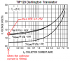
I was figuring at 12v

didn't account for transistor loss etc.
the LED caculator LED Resistor Calculator
I input 12 but inputting 10 it comes out about your figure.
Thanks
now I just need to order the parts and etch 2 boards.
planning on one 12v 40va wall wart from Mouser ($9.50)
the componets for the two boards comes out at $23.38.
etching boards using express pcb and planning on the etcheant using hydrogien perxiod and sulphuric acid. used both methods and the hydrogen perioxide mixture seems easier. takes about as long but not as messy.
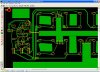
Would you like a pic or file of the pc board. most of the traces are .76mm wide.
no reason for thin traces.
I need to recheck my resistor and cap measurments.
note I lined up in rows the componets so I can set my drill press fence up and drill all the holes that are inline.I counted 13 rows for the timming circuit.
left lots of excess copper on board as no need to remove if it isn't used.
 

Attachments

  • Capture2-21-2009-4.01.24 PM.jpg
    Capture2-21-2009-4.01.24 PM.jpg
    321.6 KB · Views: 126
Status
Not open for further replies.

Latest threads

New Articles From Microcontroller Tips

Back
Top