Continue to Site

Welcome to our site!

Electro Tech is an online community (with over 170,000 members) who enjoy talking about and building electronic circuits, projects and gadgets. To participate you need to register. Registration is free. Click here to register now.

  • Welcome to our site! Electro Tech is an online community (with over 170,000 members) who enjoy talking about and building electronic circuits, projects and gadgets. To participate you need to register. Registration is free. Click here to register now.

proper transistor circuit??

Status
Not open for further replies.
ran a simulation of this circuit in TINA and it looks like it will work??
transistor is saturated??
Was contemplating using mosfets but with only 53ma draw why reinvent the wheel (I got lost reading how tos of mosfets)
going with relay or larger transistor for powering my random cabinet light circuit (see post)

Per your original,

Remember: a silicon NPN with a grounded emitter will have a base voltage of .7 if turned on hard.
 
Last edited:
Not sure of what you are describing??

Per your original,
Orginal circuit using the 2n2222 or 3904 transistors on the cd4029 outputs or the relay?


Remember: a silicon NPN with a grounded emitter will have a base voltage of .7 if turned on hard.
Audioguru suggested using a darlington transistor (TIP120) which kinda makes sense as I have a low current output from the 4029 and the load of the led array (per 8 is calculated at 53ma)
The darlington transistor will/ should do the job.
The load will be connected to the emitter not the collector (pretty sure this is what audioguru is refering to.
see my schematic
 

Attachments

  • Capture2-3-2009-8.14.13 PM.jpg
    Capture2-3-2009-8.14.13 PM.jpg
    222.8 KB · Views: 153
TINA simulation of darlington

I simulated one circuit w/ load connected to the collector and another connected to the emitter.
reall different current draws.
The base voltages on the first transistor are really different as well.
looks like the collector / load connections are best??
 

Attachments

  • Capture2-4-2009-5.02.28 AM.jpg
    Capture2-4-2009-5.02.28 AM.jpg
    352.3 KB · Views: 147
Don't you want the LEDs to slowly brighten and slowly fade? Then the LEDs should be at the emitter of the darlington transistor, the base resistor should be 10k and the base capacitor should be 100uF.
You have a 1.8k resistor feeding a 1uF capacitor that have a time constant of only 1.8ms. A 10k resistor feeding a 100uF capacitor have a nice slow time constant of 1 second.

Your simulator is giving odd voltages and currents:
1) You have 4 LEDs in series then their forward voltage is only 1.5V?? A red LED is 1.8V to 2.0V and blue and new bright green LEDs are 3.0V to 3.6V.

2) The simulation shows a very high base current for the darlington transistors that you made becaude a BD433 has much less current gain than a proper darlington transistor.

The LEDs will not brighten and fade if you use 4 LEDs in series. Use one or two LEDs in series instead.

The transistor that turns on a relay when it is dark is too simple, it does not switch but lets the relay do the switching. You need a circuit with at least 2 transistors in a Schmitt-trigger circuit.
 
forgot to make changes

The darlington transistors I put in the simulation were just that, used what TINA has which is no darlington transistors.
I was just curious.
As for the caps and resistors I failed to change out.
Will redo the led arrays with only 2 leds per series.
will repost with corrections
Thanks for your input
 
changed the resistors etc

Just outa curiosity I put 2n2222 transistors in the darlington pairs.
Put 300 ohm resistors on leds after I put in pairs.
Planning on the suggested TIP120 darlingtons.
Need to look at relay circuit more
 

Attachments

  • Capture2-4-2009-10.04.11 AM.jpg
    Capture2-4-2009-10.04.11 AM.jpg
    323.7 KB · Views: 164
Your latest simulation with 2n2222 transistors shows no currents.
You don't say what is the forward voltage of your LEDs (which I think is too low) so I can't calculate the current.

I think the simulator is too stupid to slowly brighten and fade the LEDs. It shows the 100uf capacitors fully charged all the time.
 
the LED specs

white leds

Specifications:

* Material: InGaN
* Emitting Colour:
* White
* Lens Type: Water clear Reverse Voltage: 5.0 V
* DC Forward Voltage: Typical: 3.4 V Max: 3.8 V
*
* Luminous Intensity MCD: Typ: 140,000 mcd DC Forward Current: 20mA
* Viewing Angle: 12±5degree
* Lead Soldering Temp: 260oC for 5 seconds
* Intensely Bright

If You Have Any Question, Please Contact Us.

Electrical-Optical Characteristic (Ta=25°C)
Item Symbol Condtitions Min. Typ. Max. Unit
Forward Voltage VF If=20mA 3.00 3.40 3.80 V
Reverse Current IR VR=5V / / 10 uA
Dominant Wavelength / IF=20mA / / / nm
Luminous Intensity IV IF=20mA / 140,000 / mcd
50% Power Angle / IF=20mA / 12° / degree

Absolute Maximum Ratings (Ta = 25°C)
Item Symbol Absolute Max. Rating Unit
Power Dissipation PD 100 mW
Forward Current (DC) IF 40 mA
Peak Forward Current IFP 100 mA
Reverse Voltage VR 5 V
Operation Temperature Topr -40~85°C /
Storage Temperature Tstg -10~100°C /
Lead Soldering Temperature Tsol Max. 260°C for 5 sec.

(3mm from the base of the epoxy bulb)


BLUE leds


Specifications:

* Material: InGaN
* Emitting Colour: Blue
* Lens Type: Water clear
* Reverse Voltage: 5.0 V
* DC Forward Voltage: Typical: 3.2 V Max: 3.6 V
* Wave Length: 465-470nm
* Luminous Intensity: Typ: 13,000 mcd
* DC Forward Current: 20mA
* Viewing Angle: 20±5degree
* Lead Soldering Temp: 260oC for 5 seconds
* Intensely Bright

If You Have Any Question, Please Contact Us.

Electrical-Optical Characteristic (Ta=25°C)
Item Symbol Condtitions Min. Typ. Max. Unit
Forward Voltage VF If=20mA / 3.20 3.60 V
Reverse Current IR VR=5V / / 10 uA
Dominant Wavelength / IF=20mA 465 / 470 nm
Luminous Intensity IV IF=20mA / 13,000 / mcd
50% Power Angle / IF=20mA / 20° / degree

Absolute Maximum Ratings (Ta = 25°C)
Item Symbol Absolute Max. Rating Unit
Power Dissipation PD 100 mW
Forward Current (DC) IF 30 mA
Peak Forward Current IFP 100 mA
Reverse Voltage VR 5 V
Operation Temperature Topr -40~85°C /
Storage Temperature Tstg -10~100°C /
Lead Soldering Temperature Tsol Max. 260°C for 5 sec.

(3mm from the base of the epoxy bulb)
 
I don't know why you bought LEDs with such a narrow viewing angle.

If the LEDs are 3.8V each then the total for two is 7.6V. The output high of the CD4029 is about 11.6V when it is powered from 12V and is loaded with a darlington transistor that has low current. The 10k resistor will have low current so will have a voltage drop of 0.3V so the max base voltage of the darlington is 11.3V and its emitter is 10.05V. Then the 300 ohm current-limiting resistor has only 2.45V across it and a current of only 8mA in it and in the LEDs.

If the two LEDs are 3V each then their current will be 13.5mA.

The LEDs will need to have their forward voltages measured and have a current-limiting resistor value calculated for them.
 
hi,:)

If the LED's and series resistor were connected from emitter to 0V, how would you saturate the transistor.?

are you sure ??? I did with trans and led so much . I can't remember how many times I did ??? And I did that the way I said ! and It was oke !!
 
An emitter-follower transistor makes a linear dimmer. The transistor is not used like an on-off switch when the LEDs are at the collector.
 
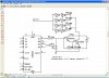
Hoangson said ‘the voltage drop on the LEDs = 2 volts’. LEDs commonly run 1.4 to 3 volts depending on color and type. I use one type of LEDs that use 5 volts. This voltage is very temperature dependent.

You used 4 LEDs in series. Series is a good way to use LEDs, not parallel. When using parallel LEDs do not use one resistor. “why did you not use only a resistor 200 ohm for this .” You did the right thing using two resistors!

Transistor= 2N2222. I could not find that data sheet because everyone makes 2N2222A.
For the 2N2222A (On-Semiconductor) the DC Current Gain at Ic=150mA and Vce=10 volts is 100 minimum, 300 typical and ? maximum. (probably 600) With a Vce of 10 volts this test is unusable! I just wanted to show that Hfe can vary 6:1 from part to part. Hfe at Ic=150mA Vce=1 volt has a minimum of 50 and typical about 150.

You are using the transistor at 50 mA so Hfe will be a little higher. If the transistor is cold the Hfe will be lower. 25C/-50C will (at 50mA) cause ½ the gain.

Because you want low Vce (Vsat) you need more base current. The gain will be lower with 0.2 volts of Vset.

Never use typical numbers. In this case use minimum numbers. Use numbers over a temperature range your project will be used at. Look at what condition the transistor will be used at. Example: Hfe at 0.1mA is 100, at 50mA Hfe=220, at 500mA Hfe=40. Look at the graph of Hfe and Ic and know this is typical not minimum. Look at the table of Hfe to see min/typ/max.

Look at the graph of Vce and Ib to see how well the transistor closes. Useing the 10mA curve we can see that with Ic=10mA and Ib=1mA the transistor is very ‘on’. At Ib=0.1mA the Vset is 0.1 volt but at 0.05mAIc the transistor starts to open up. Remember this is typical, at 25C.

I know your teacher will say use a Hfe of 100 and you need to pass the class. In the real world we look at min and max specs and use much more base current than the teacher said to.

"I know your teacher will say use a Hfe of 100 and you need to pass the class. In the real world we look at min and max specs and use much more base current than the teacher said to"
you oke ! but I assumed the beta =100. to calculate. It was not the beta of this trans is 100...It's alsway changed by temp of envirement.. !

I think with this led circuit.. when the led current is 10 or 20 ma the shining you feel almost not change.... with electric calculate + practice ---> the right or wrong !!!


and can you explain ? "not parallel. When using parallel LEDs do not use one resistor" tell me why ??

this circuit use 8 leds so.. we have not to attend the safe here for resistor ?/ It's not overheat ??
 
Last edited:
I bought the leds for strobes

for my Christmas light display. Have 15,000+ lights hooked up to a computer. The controller boards output 5v. you hook up the leds directly then flah for 50-100ms long. gives a strobe flash effect.
Well I have them, they came with 460ohm resistors for connection to 12v.
The 461ohms is what I measured with a DMM.
Your last description of electronic math amazes me (I myself am lousey at math)
Will the circuit work as drawen or do I need to make some more changes.
the 2n2222 darlington arry was just for curiosity. not a real actual simulation of a TIP120
 
The original circuit uses single LEDs that are probably 2V red ones.
Your LEDs have a fairly high voltage and two are in series. So I think your LEDs will spend most of the time fully dimmed and will begin turning on and brightening when the capacitor voltage exceeds 6V or 7V.

An extra 10k resistor from the capacitor to the positive supply will keep the voltage of the capacitor from dropping too low which turns off the LEDs.
 
Now I'm confussed???

If I connect a 10k resistor to the capictor that is going to ground then connect to the 12 supply??
the transistor won't shut off will it???
I'm thinking the resistor goes to ground and the cap connects to the 4029 output??
 

Attachments

  • Capture2-5-2009-4.59.49 AM.jpg
    Capture2-5-2009-4.59.49 AM.jpg
    160.2 KB · Views: 142
I screwed up on drawing

I messed up on the privious post.
The led arrays are supposed to be connected to the emitter not the collector (for dimming effect).
I changed the resistor/cap setup.
I THINK this will make the transistor switch off slowly for a fading effect??
size of resistor R11??
 

Attachments

  • Capture2-5-2009-7.09.55 AM.jpg
    Capture2-5-2009-7.09.55 AM.jpg
    154.8 KB · Views: 138
Didn't you see my last post?
The LEDs need 6V to 7V before they begin to light.
But the capacitor starts charging slowly when its voltage is 0V and takes a long time to reach 6V or 7V so the LEDs will be turned off for most of the time.
If a 10k to 22k resistor is added from the capacitor to 12V then the LEDs will begin brightening almost immediately after the output of the CD4029 goes high. When the output of the CD4029 goes low then the LEDs will dim.

EDIT:
In your simulation the value of R8 is like a dead short to the capacitor.
 
Last edited:
I misinturpted something??

I was thinking that w/12v connected to the cap as I have in this post the darlington would be on all the time.
Not thinking that the 4029 would sink the 12v connected to the cap.
I assume I still need R8 or do I lose it??
 

Attachments

  • Capture2-5-2009-10.10.59 AM.jpg
    Capture2-5-2009-10.10.59 AM.jpg
    155.1 KB · Views: 131
Your R8 is only 200 ohms which is like a dead short to the circuit.
R8 in a TIP120 darlington is 8000 ohms, 40 times higher with only 1/40th the current.

When the output of the CD4029 is low then the voltage divider of the 20k and 10k resistors make the capacitor have a minimum of 4V. When the output of the CD4029 goes high then the LEDs will soon begin to turn on and brighten. The 20k resistor should be 12k to 15k when the LEDs have a total forward voltage of 6V.
 
oups again

R8 was what the last componet was in TINA. Forgot to change as per TIP120 data sheet (I plan on using the TIP120 instead of constructing my own darlington pair.
I changed the 20K to 15K
I need to recheck my drawings
 

Attachments

  • Capture2-5-2009-5.41.46 PM.jpg
    Capture2-5-2009-5.41.46 PM.jpg
    154.9 KB · Views: 136
Status
Not open for further replies.

Latest threads

Back
Top