synchronus
New Member
hey
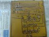
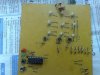
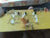
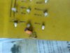
me making an elctronic tic tac toe game by using PIC16F628.
I have got the asm code for my program from
http://talkingelectronics.com/projects/TicTacToe/files/BlankF84.asm
but when ever i compile it to hex codes the compiler shows some syntax error
in asm code.
Is the codes right?? sometimes even compiler cant compile the whole program.
plz. anyone can help it out m tagged with this problem for last 2 month.
for further refrence
Tic Tac Toe