Continue to Site

Welcome to our site!

Electro Tech is an online community (with over 170,000 members) who enjoy talking about and building electronic circuits, projects and gadgets. To participate you need to register. Registration is free. Click here to register now.

  • Welcome to our site! Electro Tech is an online community (with over 170,000 members) who enjoy talking about and building electronic circuits, projects and gadgets. To participate you need to register. Registration is free. Click here to register now.

Problems wiring an analog switch

Status
Not open for further replies.

vielle568

Member
Can anyone tell me where I'm going wrong?
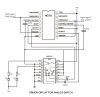
I'm trying to use a Max4619 analog switch to pulse two audio signals for a musical instrument that I'm building. At the moment I can't quite figure out how to trigger the Max4619. It requires an input signal that changes from ground to Vcc to toggle the switch. I used a 556 configured as a bistable to obtain the two trigger signals and it worked fine on the breadboard but now its all soldered in place on the PCB something has changed. I've put some LEDs across the switches to monitor their state. They work correctly, but only if I touch the case of the 556 with my finger! There seems to be some kind of electrostatic charge that's interferring with the circuit, but how do I get around this problem?
Any bright ideas? Thanks!
 
Hello dknguyen,
The frist part of the circuit is not shown on the schematic as this is working correctly, but I'll describe it anyway. Basically an IR LED is mounted opposite a IR sensor and between the two there's a wheel that turns with holes bored around the perimeter. The light pulses through to send signals to trigger a comparator, and this then negative edge triggers a monostable 555. The output pulse from the 555 is sent to two LN2917 speed switches that are used as tachometers to monitor the wheel speed. One is set up to trigger as soon as the wheel starts to turn and the other can be adjusted to trigger at various preset speeds.
The output signal from the LN2917 is +5 volts and drops to near ground when the speed switch toggles. This signal didn't activate the analog switch so I tried using a timer (a 556 double timer for the two signals) set up in bistable configuration to act as a flip-flop. It seemed to work OK using a single 555 on the breadboard, but when the whole thing was assembled with the 556 the circuit didn't function correctly. The LEDs were very irratic and eventually I found that the solution was to touch the 556 with my finger and everything would work correctly! The wiring is as shown on the diagram. I've changed the ICs and I can't see and other errors. Any suggestions?
Vielle568
 

Attachments

  • ANALOGSW.JPG
    ANALOGSW.JPG
    83.5 KB · Views: 190
The last time someone came to me with a project with that problem, he had overheated a land on the PWB causing an open where a trace was cracked and his finger was providing the connection when he put his finger on it.
 
OK ccurtis,
I'll check out the wiring just to make sure, but this isn't on a regular PCB with etched foil below, its an experimental project and the connections are all jumpered underneath the board. I'll double check to make sure. The circuit will only work if I touch the 556 chip; there's no effect if I try grounding the other ICs.
vielle568
 
Status
Not open for further replies.

Latest threads

New Articles From Microcontroller Tips

Back
Top