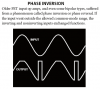
Continue to Site

Welcome to our site!

Electro Tech is an online community (with over 170,000 members) who enjoy talking about and building electronic circuits, projects and gadgets. To participate you need to register. Registration is free. Click here to register now.

  • Welcome to our site! Electro Tech is an online community (with over 170,000 members) who enjoy talking about and building electronic circuits, projects and gadgets. To participate you need to register. Registration is free. Click here to register now.

problem with PWM signal

Status
Not open for further replies.
yes i understand clearly what yo mean and i will get you the scope pics but there is a small issue and it is that i use a pc scope software called visual analyzer 2011 version and i caliberated it by inputing acurate 1VAC into my sound card input so as to be able to measure wave forms in volts and peak voltages so i dont know if you know about this software and how to read the scale.
for example the bubba sine wave reads 50hz with peak to peak voltage 0.9V powered fron a 12V lead acid battery and now considering the calibration using 1V which is the maximum a sound card can take so as not to damage it,how do you then get the actual peak to peak in terms of DC.
i dont knoe if you get what am trying to say but i will get you the scope pics asap.thanks so far

Hello,

You mean the scope isnt a real scope but a sound card 'scope' ?

That might not help us at all here because we need to see DC levels.
 
The input signals to the comparator do not need to have a large amplitude and do not need to go to ground. The comparator has a very high voltage gain of 200,000 times so the input signals only need to have the same bias voltage (half the supply voltage) so that one goes higher than the other and lower than the other. The output of the comparator is a switch that goes either completely high or very low, never at a partial voltage. See my attachment.

I mentioned rail-to-rail opamps because they are common here and the sample circuit that was posted used them. The resistor values in the sample circuit must be changed to reduce the levels so that clipping does not occur.
i understand better now having seen your attachment thanks a lot but what sample circuit are you talking about and what resistor values need to be changed?
 
unfortunately yes its a sound card scope so i know it might be difficult.

Hi again,

There are ways to see DC on an AC scope, but you'd have to build a little circuit up and that would take some time. For that kind of circuit there has to be a little bandwidth wiggle room too though so im not sure how well this would work with a 'sound card' scope. For very low frequencies maybe, like 50Hz, it might work though.

Another idea without a scope is to simply lower the frequency down into the sub Hertz on either oscillator just for the testing. If the triangle was running at 0.1 Hz (one tenth of one Hertz or 1/10 Hz) then it would take 2.5 seconds to reach the peak, and 5 seconds to reach the negative peak, then another 5 seconds to reach the positive peak again, etc., so you could view this with a DC voltmeter assuming you have one.
Same with the sine wave. With very low frequency like that you could view the peaks on the DC meter. That would tell us if the waves are 'really' within spec.

See what i suspect is that the input waves are not of the right amplitude, so we would need a way to observe that. If we cant observe it then we have to hope to get lucky by swapping values. The way this would normally be trouble shot is a DC coupled scope would be used.
Alternately you could build up a little peak reading meter using a DC meter and a fast diode and small capacitor.

We talk about the amplitudes because once the amplitudes are right the circuit will definitely work right, unless there is still a bad connection or something else simple like that.

Oh yeah another idea is to substitute each wave with a pot and set the pot to about 1/2 Vcc. So the pot arm would be connected to one input of the comparator and either the triangle OR the sine wave would connect to the other terminal. The output of the comparator should switch on and off at the same frequency as the input wave unless something really isnt right.
 
Last edited:
Hi again,

There are ways to see DC on an AC scope, but you'd have to build a little circuit up and that would take some time. For that kind of circuit there has to be a little bandwidth wiggle room too though so im not sure how well this would work with a 'sound card' scope. For very low frequencies maybe, like 50Hz, it might work though.

Another idea without a scope is to simply lower the frequency down into the sub Hertz on either oscillator just for the testing. If the triangle was running at 0.1 Hz (one tenth of one Hertz or 1/10 Hz) then it would take 2.5 seconds to reach the peak, and 5 seconds to reach the negative peak, then another 5 seconds to reach the positive peak again, etc., so you could view this with a DC voltmeter assuming you have one.
Same with the sine wave. With very low frequency like that you could view the peaks on the DC meter. That would tell us if the waves are 'really' within spec.

See what i suspect is that the input waves are not of the right amplitude, so we would need a way to observe that. If we cant observe it then we have to hope to get lucky by swapping values. The way this would normally be trouble shot is a DC coupled scope would be used.
Alternately you could build up a little peak reading meter using a DC meter and a fast diode and small capacitor.

We talk about the amplitudes because once the amplitudes are right the circuit will definitely work right, unless there is still a bad connection or something else simple like that.

Oh yeah another idea is to substitute each wave with a pot and set the pot to about 1/2 Vcc. So the pot arm would be connected to one input of the comparator and either the triangle OR the sine wave would connect to the other terminal. The output of the comparator should switch on and off at the same frequency as the input wave unless something really isnt right.
hello Sir you said the suspect that the wave form is not at the right amplitude could you explain further?
i did some testing on my own and from the calibrated reading the scope reading shows that the amplitude of the sine wave is far greater than the amplitude of the triangle wave and to be sure i tested a normal square wave inverter oscillator which i have used on an inverter i owned and it showed high amplitude reading similar to the sine wave using the calibration settings so am wondering could this be a factor?
oh and one more thing when i removed the triangle wave from the non inverting input of the comparator leaving that pin empty with the sine wave still connected to the inverting input i got a square wave at the output meaning my comparator works fine so it has maybe to do with their amplitudes as you may have said.will continue testing later as i must get to the bottom of this.
 
i understand better now having seen your attachment thanks a lot but what sample circuit are you talking about and what resistor values need to be changed?
You posted the sample Bubba oscillator in your reply #7. It says that it is based on rail-to-rail opamps that you cannot get. R5, r6, R7 and R8 need to be changed so that an ordinary TL08x opamp will work without clipping.

The peak-to-peak voltages of the triangle and sine-wave should be about the same. Their average DC voltages MUST be the same.
 
ok,the thing is but i built the oscillator and i have a clean sine wave at the output and if you look at the actual bubba i later posted i used R=1.5M and R= 330k for the gain setting.what am saying is i have a very clean sine wave before and after bufering but when you say clipping does it mean that the compartor is what does the clipping.
 
The comparator is a switch that gives an output that is high or low.
I do not know if your sinewave or triangle waveforms are clipping because you do not have a REAL oscilloscope.

I deleted my discussion about using a TL082 as a comparator because it was in another thread. You are using an LM393 REAL dual comparator that does not have "Opamp Phase Inversion".

Your software oscilloscope "samples" and has "Hanning Smoothing" that messes up the PWM waveform.
 

Attachments

  • opamp phase inversion.PNG
    opamp phase inversion.PNG
    15.3 KB · Views: 163
Last edited:
hello Sir you said the suspect that the wave form is not at the right amplitude could you explain further?
i did some testing on my own and from the calibrated reading the scope reading shows that the amplitude of the sine wave is far greater than the amplitude of the triangle wave and to be sure i tested a normal square wave inverter oscillator which i have used on an inverter i owned and it showed high amplitude reading similar to the sine wave using the calibration settings so am wondering could this be a factor?
oh and one more thing when i removed the triangle wave from the non inverting input of the comparator leaving that pin empty with the sine wave still connected to the inverting input i got a square wave at the output meaning my comparator works fine so it has maybe to do with their amplitudes as you may have said.will continue testing later as i must get to the bottom of this.

Hi,

You have to do some more testing, but the tests have to be carefully planned and executed. It's not a good idea to leave a pin open like that, but rather connect two resistors at least. The two resistors should be of equal value like 1k and one goes to +Vcc and one goes to ground, and the center goes to the comparator pin.

You should also test the other wave this way too. Since you are getting a square wave that's great, but you really have to connect the other pin to the resistors and also check the frequency of the square wave you see.

The triangle wave positive peak amplitude must be greater than the sine wave positive peak. That's so that we dont miss a pulse near the sine peaks. The triangle wave negative peak should be less than the sine wave negative peak. So in general the triangle amplitude should be slightly higher than the sine amplitude. So for example if the sine goes from 2.5v to 7.5v (centered at 5.0v) then the triangle should go from around 2.4v to 7.6v for example. This small but measurable difference ensures that the output PWM is always dependent on the sine amplitude and not on any noise.

So add the two resistors and test both the sine and triangle wave, checking the output square wave frequency for both tests.
hello Sir i did what you asked and tested both sine and traingle waves using voltage divider and heres the results
for the sine wave with frequency 50hz to input of comparator and dc voltage of (1/2 of Vcc from a 12V lead acid battery) i got a square wave of frequency 50hz at the output and i noticed that when i either increased or decreased the voltage to a certain level the square wave disappered and when i disconnected the sine wave from the input to the compartor with the DC voltage still connected the square wave also disappeared so this means the sine wave is ok?
as for the triangle well no luck with this as i did not get a a square wave even when i adjusted the dc voltage levels up or down so what does this say about the triangle?
one more thing, i get the part where you said the peak amplitude of the triangle has to be higher than the sine wave but the part about the triangle negative peak being lesser is what i dont get.i thought the triangle wave should totally cover the sine wave?
 
Hello,

Well the comparator is not detecting the triangle wave for some reason. Maybe the connection does not make it to the chip itself. Check that carefully. You should get a square wave for the triangle too when the resistors are connected to the other input (and nothing else to that pin).

The triangle has to be less than the sine wave near the bottom of the sine wave. It has to be greater than the sine wave too near the top of the sine wave. That's so the triangle effectively chops up the sine wave no matter where the sine is in amplitude. It must be capable of going above the sine and below the sine or else one part of the sine may not get compared correctly and thus there will be a missing pulse which would result in output PWM distortion. If the PWM was filtered back into a sine, there would be excess distortion in the resulting sine wave.
With proper triangle amplitude, the resulting reconstructed sine wave would have minimal distortion.
hello sir,i have been testing again the triangle wave with a DC reference voltage as you said and i noticed that instead of getting a square wave the triangle wave seems to grow in amplitude up to a point and shrink away as i adjust the dc voltage up or down and i have checked the pins for bad connection but evrything is allright as the comparator recieves the triangle wave at the input and the compartor is powered fully at the pin 8 but for some reason square waves are not coming out.i am beginning to think that what audioguru said before about the pc software scope messing up the PWM signals especially when i input both sine and triangle waves into the comparator because everything seems allright to me.you can check out the picture of the triangle wave at about 4500hz going into the comparator and unless my eyes are not good i can pretty much say that that is a triangle wave form.
guess i will never know what is really happening until i get a real scope.thanks for everything so far.
 

Attachments

  • trianglewave.jpg
    trianglewave.jpg
    1.7 MB · Views: 161
A 4500Hz triangle wave has harmonics up to at least 90kHz and is very clear when its bandwidth is almost 1MHz. Your sound card scope filters it into a 4500Hz sinewave that is modulated by the sampling frequency of the scope.

Your soundcard probably cuts frequencies above 20kHz so it is useless at these high frequencies.
Try using 200Hz for the triangle and use 10Hz for the sinewave. Then the output from the comparator will be a squarewave if a sine or triangle is inputted and will be a PWM waveform if both are inputted.
 
Hi again,

Yes with a 'pseudo' scope it is harder to troubleshoot this thing. But i think if you do what audioguru suggested (decrease frequency) you will see better results. The main problem with a sound card scope is that the sound card has very very limited bandwidth, so you must stay much lower in frequency to be able to see anything that resembles the real waveform.

We could design other experiments too. Comparators are fast, so we could design a small circuit that looks for a certain voltage level in the triangle. By sync'ing to the zero crossing, we could look for certain characteristics at the output of the comparator.

Of course you also have the choice of going to a super low frequency and just using a DC volt meter. I assume you have a DC meter, like a digital meter. At 0.1 Hz you can see the wave go up and down even on a meter. If that's not slow enough, then decrease to 0.05Hz, and if that's not slow enough, 0.01Hz, etc., until you can see the wave go up and down on the meter. By noting the response of the meter vs time, you can deduce the waveform. More importantly, you can measure the true peaks and valleys.
 
I doubt that a sound card can go much below 20Hz. 20Hz might be at -3dB and 10Hz might be at -6dB (half the level of higher frequencies).
 
Hi audioguru,

Yes you are right, so he will have to use the meter for measuring sub Hertz frequencies like 0.1Hz or lower.
 
Hi audioguru,

Yes you are right, so he will have to use the meter for measuring sub Hertz frequencies like 0.1Hz or lower.
hello sir,you and audio guru were right i lowered the triangle wave to about 1000Hz and when i compared it to a DC refrence voltage i got PWM wave form at same 1000Hz.
i then further reduced the triangle to 500Hz and then compared it to a sine wave and low and behold i got PWM at about 500Hz out an when i varied the amplitude of the sine wave i saw what you meant when you said the triangle amplitude has to be higher than the sine wave so that the sine i chopped accordingly and we dont miss a pulse.it turns out that the pc scope has issues going higher than 1000Hz so it messes up the PWM.
would have to get a real scope.wow thats going to cost me but would like you to recommend the type of scope i should get should i ever attempt to get one interms of bandwith and stuff like that.
i am grateful for the help you and audioguru has given me so far in figuring this out.i now have a sense of relief knowing that my connections were right in the first place.
 

Attachments

  • triangleDCPWM.jpg
    triangleDCPWM.jpg
    1.8 MB · Views: 170
  • triangleSinePWM.jpg
    triangleSinePWM.jpg
    1.6 MB · Views: 168
Where does your scope connect to when it shows "trianglesine.jpg"? I ask because it shows an amplitude-modulated PWM (the up and down waves) when PWM should not have any amplitude modulation. I guess it is caused because the pc scope is AC-coupled instead of DC-coupled.
 
Where does your scope connect to when it shows "trianglesine.jpg"? I ask because it shows an amplitude-modulated PWM (the up and down waves) when PWM should not have any amplitude modulation. I guess it is caused because the pc scope is AC-coupled instead of DC-coupled.
lets assume the pc scope is DC-coupled,i have a some questions
what do you mean by where does scope connect t0 i dont quite get it?
also when you say it should not have amplitude modulation what does it mean and why so?
 
Right from the first post, it looks like the ground of the scope has AC content, as if the triangle wave has been modulated with a lesser frequency, This happens with crappy power supplies... or your scope ground coupling isn't right...
 
Status
Not open for further replies.

Latest threads

New Articles From Microcontroller Tips

Back
Top