Continue to Site

Welcome to our site!

Electro Tech is an online community (with over 170,000 members) who enjoy talking about and building electronic circuits, projects and gadgets. To participate you need to register. Registration is free. Click here to register now.

  • Welcome to our site! Electro Tech is an online community (with over 170,000 members) who enjoy talking about and building electronic circuits, projects and gadgets. To participate you need to register. Registration is free. Click here to register now.

problem with PWM signal

Status
Not open for further replies.

maicael

Member
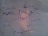
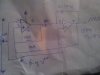
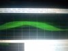
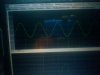
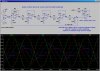
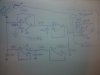
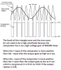
i built a bubba oscillator of 50hz frequency and had to buffer the point where the signal has lowest distortion using TL084 for the original oscillator and TL082 for the buffer circuit.i then built a triangle wave oscilltor of about 3000hz - 10000hz range and set it to about 5000hz but when i wired up the comparator using LM393 to get PWM signal i am getting strange signal and i dont know what else to do here are the pics of the circuit.
am kind of confused on what am doing wrong since i was able to get the bubba to oscillate well at 50hz and the trinagle to oscillate well between those frequencies and keeping it at 6000hz for pwm but i dont know whats happening.
 

Attachments

  • LM393 comparator.jpg
    LM393 comparator.jpg
    1.4 MB · Views: 1,148
  • TL082 triangle wave.jpg
    TL082 triangle wave.jpg
    1.5 MB · Views: 798
  • strange wave form.jpg
    strange wave form.jpg
    1.1 MB · Views: 533
Hello,

Can you show some scope pics of the two inputs to the comparator, the non inverting and inverting terminals?
And is that scope pic you had shown of the output of the comparator or something else?

If the comparator is powered ok and working ok it will definitely work at 50Hz. You might need some hysteresis though too. Note that if your input signals swing from -8v to +8v for example, you can not connect your comparator to +5v and ground or even not to +10v and ground. The comparator would have to be connected to +10 and -10 volts as well. If you need a PWM signal that swings from 0v to +5v or from 0v to +10v, then we have to do a little level shifting.
 
Last edited:
Hello,

Can you show some scope pics of the two inputs to the comparator, the non inverting and inverting terminals?
And is that scope pic you had shown of the output of the comparator or something else?

If the comparator is powered ok and working ok it will definitely work at 50Hz. You might need some hysteresis though too. Note that if your input signals swing from -8v to +8v for example, you can not connect your comparator to +5v and ground or even not to +10v and ground. The comparator would have to be connected to +10 and -10 volts as well. If you need a PWM signal that swings from 0v to +5v or from 0v to +10v, then we have to do a little level shifting.
hello i have been following the thread on the guy who wants to build a 200Mhz triangle wave and i saw the part where he connected a triangle wave to the noninverting input of the comparator in my case is pin 3 of LM393 and the 50hz sine wave to the inverting input that is pin 2 to get a PWM signal and i just followed his lead.
my input signals cant swing from negative to positive since am connecting it using a single supply of +12v and setting the reference to +6v thereabout(half of vcc) for both sine and triangle waves so i dont understand why it should swing from negative to positive maybe you could enlighten me you know better than me and you are more knowledgeable.
how do we do this hysterisis and level shifting because i need the signal from 0v to +10v or higher.
and yes that scope pic my friend is unfortunaltely the output of the comparator where the PWM signal is supposed to come out from.i even changed the LM393 several times just to be sure that it was not at fault but it is still thesame output.
 
Hello again,

Hysteresis is something often added to comparators that have to operate in noisy environments. We can add this if you like, but i would think it would work better than that even without hysteresis unless you happen to be in a very unfavorable environment.

Note that i had said "If your signal swings from -8v to +8v", i did not state that your signal swings that much. That was a possibility that i thought you might want to look into, but that's only if you were using a plus and minus supply.
Since you are not using a plus and minus supply, you dont have to worry about that.

If the input sine wave ALSO goes from 0 to some positive level, then you should be ok with this. So check and see that you really have a sine wave that goes from close to 0 to some positive level like 8 volts. If it goes negative, it may burn out the comparator chip.

Assuming it does go from 0 or say +1v to say +8v, then it should be working as is. If it is not working then check the power supply to make sure it makes contact with the pins on the actual comparator IC pins. Sometimes sockets do not make contact even though it looks like they do. So you have to probe right on the IC pin itself, not on the PC board. If you measure the right voltage then verify that the ground pin really makes it to ground as well. Also check the power supply voltage to make sure it is stable at all times. It may need some extra capacitive filtering.
There really cant be much else wrong except for a connection somewhere so you have to check carefully.
There is always a chance that all the comparators you have are burnt out or just defective, so you can test one with say two pots and a pullup resistor and make sure the output goes high and low as it should with the two pots.

If it does turn out that your sine wave went negative, then fix that and replace the comparator again with a known good one. Since you are having such a problem with this part of the circuit, test the comparator with two pots just to make sure.

If the comparator is good, then it must be one of the input leads is not making it directly to the comparator input where it should. It could also be the ground lead however, which has to be common to all three circuits (comparator, triangle output, sine wave).
Remember to test the signals right on the chip pins not on any board or socket terminal. That means the probe goes right to the pin on the package of the IC itself where it exits the package plastic. Multilayer PC board pads may not make connection with the IC or socket pins either, and bad solder joints even on single sided PC boards dont work many times, or sometimes work intermittently. Hard wired point to point wiring can sometimes have wires with leads broken inside but the insulation hides this. Many of these faults can be found by simply testing on the IC pins themselves rather than some other point.

If the IC chip is tested and found to be working and all the proper signals are getting to the chip pins themselves, then the circuit must work.
 
Last edited:
The schematic for the Bubba oscillator is not shown. The schematic for the buffer amp for it is not shown and explained why it is needed.

The maximum allowed input (input common mode voltage range on the datasheet) to the LM393 comparator is 0V to (+12V - 1.5V=) +10.5V so the triangle wave is probably OK but we know nothing about the sinewave and its buffer amp.

The LM393 comparator output is overloaded with a 1k load so its max output current is trying to be 12mA but its datasheet shows it saturating with a 4mA or less load.

The circuits here do not have very important supply bypass capacitors.

The scope is a software one that is messing up the output waveform because its sampling frequency is much too low and maybe because it is set for an AC input instead of a DC input. The software scope has filtering that might be messing up the waveform. 0V and any mention of how many volts per line are not shown.
 
The circuits here do not have very important supply bypass capacitors.

Yes. This is extremely important. When the comparator changes state, it will send transient voltages back into the power supply lines which will interfere with the other signals. You need to connect a 0.1 µF capacitor from the comparator chip Vcc pin 8 to ground pin 4, as close to the chip as possible.

Also, are your signals coupled to the comparator inputs through DC blocking capacitors? If so, the inputs will need to have bias circuitry added (resistor voltage dividers) so that the inputs don't float up to +Vcc or down to ground levels.
 
The schematic for the Bubba oscillator is not shown. The schematic for the buffer amp for it is not shown and explained why it is needed.

The maximum allowed input (input common mode voltage range on the datasheet) to the LM393 comparator is 0V to (+12V - 1.5V=) +10.5V so the triangle wave is probably OK but we know nothing about the sinewave and its buffer amp.

The LM393 comparator output is overloaded with a 1k load so its max output current is trying to be 12mA but its datasheet shows it saturating with a 4mA or less load.

The circuits here do not have very important supply bypass capacitors.

The scope is a software one that is messing up the output waveform because its sampling frequency is much too low and maybe because it is set for an AC input instead of a DC input. The software scope has filtering that might be messing up the waveform. 0V and any mention of how many volts per line are not shown.
here is a picture of the bubba and the scope wave form.changes made to the bubba are R5= 1.5meg R6=330k all other values remain thesame and like i said i used TL084 for the mainn sine wave and then TL082 fot the buffer circuit consisting of R8 and R7 and i powered from a 12v source.i bufferd the output because at that point it has the least amplitude and lowest distortion so i read about bubba oscillators and tested it.
is there a better comparator to use out there whose maximum input is probably higher?
as for the bypass capacotors this crossed my mind alot and i will definitely include them but what values do you recommend
i guess i dont need the 1k resistors in the comparator then.
a
As for the software it is visual analyzer 2011 and am still checking it out as am not used to it yet and dont now all the fuctions and yet to even caliberate maybe with time will get some understanding
 

Attachments

  • sine wave.jpg
    sine wave.jpg
    1 MB · Views: 415
  • BubbaB.jpg
    BubbaB.jpg
    547.7 KB · Views: 505
You are very confusing when you post a Bubba oscillator with the wrong opamps (not rail-to-rail), different resistor values, a different supply voltage and do not show how its first opamp is biased.
It is too bad that your software scope cannot show DC levels and peak-to-peak voltages.

The 1k resistor in the comparator is its important collector load. Its value is too low for a weak LM393, use 3k or 3.3k instead. Reduce the input levels to the comparator a little then it will work perfectly.
 
Hello again,

I am still waiting for a scope pic of both inputs. If we could see the two inputs as they arrive at the comparator, we can then tell if the signals are of the proper level or not. If the sine swings from 0 to +5v and the comparator power supply is ground (0v) and +10v then it should work ok because the comparator can work with input voltages from ground (0v) up to Vcc-1.5v, which for a 10v supply is 8.5 volts. So the max input to the comparator has to be 8.5 volts with a 10v supply, and 0v for the min input. So the sine can swing from 0 to +5v but NOT from 0 to +10 volts for example. Same for the triangle, 0v is the min and 8.5v is the max.

If you happen to be using a +5v supply for the comparator, then the input limits are 0v and 3.5v which as you can see is much lower. If the sine swings from 0 to +5v then that would not work when using a +5v power supply.

So you see why i want to see the two inputs on the scope because that tells the WHOLE story and we can probably clear this up in one more reply post. You should also measure the comparator power supply voltage right on the IC chip pin just to make sure, and report that value back here too.

Of course power supply filtering is always a must for circuits like these and actually for most circuits these days. We can also add some hysteresis later if you like once we get the basic operation going well.
 
I think the supply for the entire circuit is a 12V lead-acid battery (13.8V) and all circuits use this supply.
I think the circuit will be a pure sinewave inverter when it is finished.

A REAL scope will show the actual output voltages of the oscillators. The output of a TL082 or TL084 opamp cannot go to 0V.
 
Hi,

Yes there are a number of possible problems that could be here, but as i said before we need to see the two inputs to the comparator on the scope and that will clear this whole mess up.

So how about two scope pic's of the two inputs now?
 
I think the supply for the entire circuit is a 12V lead-acid battery (13.8V) and all circuits use this supply.
I think the circuit will be a pure sinewave inverter when it is finished.

A REAL scope will show the actual output voltages of the oscillators. The output of a TL082 or TL084 opamp cannot go to 0V.
sorry for confusing you with that bubba picture.i thought i explained well enough,so heres the actual circuit i used to clear things up.all circuits powered from a 12V lead acid battery as you said.
1)pls can you expalain what you mean by TL082 an TL084 opamp cannot go to 0V and rail to rail opamps?
2)f you know a list of rail to rail opamps ior where i can search i would be glad.the problem is here i was able to get only TL084 and TL082 which seeems to be common where i stay and even those who sell it dont know what an opamp is. i could not even find the MC33172 you once used in your PWM circuit to drive a motor so getting a list would mean i have a pool of options to search around for.
3)do you know of any scope software that can show peak to peak and what other comparator can i use or do i stick to the 393?
hoe my questions are not too much.Bear with me.
 

Attachments

  • actual bubba.jpg
    actual bubba.jpg
    897.4 KB · Views: 523
Last edited:
Hi,

Yes there are a number of possible problems that could be here, but as i said before we need to see the two inputs to the comparator on the scope and that will clear this whole mess up.

So how about two scope pic's of the two inputs now?
hello Sir please when you mean scope inputs do you mean after i have connected the triangle wave and the sine wave to the comparator inputs pins?
do you want to see if the signal distorts or something like that.may be a little explanation here because i posted a picture of the sine wave which i input into the comparator but maybe i dont get you.
Any way i will try to get you the scope inputs as they arrive the comparator if i get what you mean hopefully later because right now i need to watch a game of football(cant help it).
bear with me.
 
1)pls can you expalain what you mean by TL082 an TL084 opamp cannot go to 0V and rail to rail opamps?
Your lead acid battery is about 13.8V. A rail-to-rail opamp is usually Cmos and its inputs and output can go from 0V to 13.8V when the load current is low.
The TL082 dual and TL084 quad have Jfets at the inputs and has many ordinary transistors as emitter-followers at the output so the input can go down to about +4V and up to 13.8V and the output can go down to about +1.3V and up to about +11.8V.

2)f you know a list of rail to rail opamps ior where i can search i would be glad.the problem is here i was able to get only TL084 and TL082 which seeems to be common where i stay and even those who sell it dont know what an opamp is. i could not even find the MC33172 you once used in your PWM circuit to drive a motor so getting a list would mean i have a pool of options to search around for.
American parts distributors like Digikey have a very good search engine. I doubt that you can buy rail-to-rail opamps in Nigeria.

3)do you know of any scope software that can show peak to peak and what other comparator can i use or do i stick to the 393?
I have a REAL scope that works perfectly. I have never seen and have never used a software scope. I think you have your software scope set up for AC signals when it must be set for DC signals and calibrated.
The LM393 comparator will work perfectly on a pcb (but not on a breadboard) when its collector resistor is 3.3k ohms.
 
Last edited:
I think the supply for the entire circuit is a 12V lead-acid battery (13.8V) and all circuits use this supply.
I think the circuit will be a pure sinewave inverter when it is finished.

A REAL scope will show the actual output voltages of the oscillators. The output of a TL082 or TL084 opamp cannot go to 0V.
hello audioguru a thought just crosssed my mind,you said that the opamps(tl084 and tl082) i used are not rail to rail which means that there is a posibilty that the amplitude of the triangle wave and the sine waves will not be that high which will result in a low PWM signal amplitude.with a rail to rail i would be able to get amplitudes very high because i would need the amplitudes to be as high as possible and it is important for the waves(sine and triangle) to go from 0V to as high as possible to give PWM going from 0V too or am i missing something here?
 
The difference between using a rail-to-rail opamp with an output of 13.8V p-p is small compared to using a TL08x with an output of 10.5V p-p.
The output level from the comparator will be exactly the same!

EDIT: The voltage gain of an LM393 comparator is typically 200,000 so when the inputs have a very tiny voltage difference then the output switches completely high or very low. The output of a comparator is never at a partial voltage.
 
Last edited:
hello Sir please when you mean scope inputs do you mean after i have connected the triangle wave and the sine wave to the comparator inputs pins?
do you want to see if the signal distorts or something like that.may be a little explanation here because i posted a picture of the sine wave which i input into the comparator but maybe i dont get you.
Any way i will try to get you the scope inputs as they arrive the comparator if i get what you mean hopefully later because right now i need to watch a game of football(cant help it).
bear with me.

Hello,

Yes i asked about two scope pics:
1. The non inverting terminal of the comparator
2. The inverting terminal of the comparator

This is after the triangle and sine has been connected.

The scope pics however have to be 'GOOD' pics, where we can see the scales clearly, especially the vertical scale. We want to be able to see the wave and be able to read off the amplitude in volts for the min, max, and middle voltage. So we'd be able to see the max of say the sine and look to the left and see the voltage written on the scope grid and should be able to read it clearly. This is very important.
You should connect the scope to the pins of the comparator too, not the socket or board.
You should also measure the positive supply getting to the comparator right on the pin.

If the voltage to the comparator is ok and the signals are within range, then it has to work unless something very simple is wrong like a bad connection. Do you understand this?
 
The difference between using a rail-to-rail opamp with an output of 13.8V p-p is small compared to using a TL08x with an output of 10.5V p-p.
The output level from the comparator will be exactly the same!

EDIT: The voltage gain of an LM393 comparator is typically 200,000 so when the inputs have a very tiny voltage difference then the output switches completely high or very low. The output of a comparator is never at a partial voltage.
is it important that the sine wave and triangle start from 0V to their respective voltages in order to make the PWM signal go from 0V?
why i aked is because since the output level of the comparators will be exactly thesame ,then it does not matter if i use a rail to rail.
The TL08x works fine but since the TL08x dont go all the way down to 0V will the PWM signals not go all the way down to 0V assuming the signals is lets say 10V p-p using this opamp or it does not matter the opamp because the comaprator will always output a signal going from 0V?
 
Hello,

Yes i asked about two scope pics:
1. The non inverting terminal of the comparator
2. The inverting terminal of the comparator

This is after the triangle and sine has been connected.

The scope pics however have to be 'GOOD' pics, where we can see the scales clearly, especially the vertical scale. We want to be able to see the wave and be able to read off the amplitude in volts for the min, max, and middle voltage. So we'd be able to see the max of say the sine and look to the left and see the voltage written on the scope grid and should be able to read it clearly. This is very important.
You should connect the scope to the pins of the comparator too, not the socket or board.
You should also measure the positive supply getting to the comparator right on the pin.

If the voltage to the comparator is ok and the signals are within range, then it has to work unless something very simple is wrong like a bad connection. Do you understand this?
yes i understand clearly what yo mean and i will get you the scope pics but there is a small issue and it is that i use a pc scope software called visual analyzer 2011 version and i caliberated it by inputing acurate 1VAC into my sound card input so as to be able to measure wave forms in volts and peak voltages so i dont know if you know about this software and how to read the scale.
for example the bubba sine wave reads 50hz with peak to peak voltage 0.9V powered fron a 12V lead acid battery and now considering the calibration using 1V which is the maximum a sound card can take so as not to damage it,how do you then get the actual peak to peak in terms of DC.
i dont knoe if you get what am trying to say but i will get you the scope pics asap.thanks so far
 
is it important that the sine wave and triangle start from 0V to their respective voltages in order to make the PWM signal go from 0V?
why i aked is because since the output level of the comparators will be exactly thesame ,then it does not matter if i use a rail to rail.
The TL08x works fine but since the TL08x dont go all the way down to 0V will the PWM signals not go all the way down to 0V assuming the signals is lets say 10V p-p using this opamp or it does not matter the opamp because the comaprator will always output a signal going from 0V?
The input signals to the comparator do not need to have a large amplitude and do not need to go to ground. The comparator has a very high voltage gain of 200,000 times so the input signals only need to have the same bias voltage (half the supply voltage) so that one goes higher than the other and lower than the other. The output of the comparator is a switch that goes either completely high or very low, never at a partial voltage. See my attachment.

I mentioned rail-to-rail opamps because they are common here and the sample circuit that was posted used them. The resistor values in the sample circuit must be changed to reduce the levels so that clipping does not occur.
 

Attachments

  • PWM comparator signals.png
    PWM comparator signals.png
    28.1 KB · Views: 573
Status
Not open for further replies.

Latest threads

Back
Top