Continue to Site

Welcome to our site!

Electro Tech is an online community (with over 170,000 members) who enjoy talking about and building electronic circuits, projects and gadgets. To participate you need to register. Registration is free. Click here to register now.

  • Welcome to our site! Electro Tech is an online community (with over 170,000 members) who enjoy talking about and building electronic circuits, projects and gadgets. To participate you need to register. Registration is free. Click here to register now.

Problem with 555+4017 circuit (LEDs always on)

Status
Not open for further replies.
I guess you have not tried it.
The outputs of monolithic devices are very well matched.

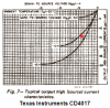
Yes, I have tried it and I have seen the variances with devices with higher drive capability than this one. No, the transistors are not very well matched. If they were, the characteristic would not vary 50%, or more, in the case of the TI device and would be defined by other manufacturers. They are not even well matched. Devices with very well matched transistors are expensive and individually tested for matching.

We do this for fun, not for profit.
When I did it for profit then every single circuit worked perfectly. Now that I do it for fun, every single circuit still works perfectly.

You made the statements and I responded to them, kindly. Nothing more, nothing less. That's what forums are for.

By the way, it is disingenuous to quote posters by putting words in their mouths that you said, in addition to what they said.
 
I could not design the circuit myself as I have no ability in this field. But I have found this circuit on the web:

I designed this in my head before building it and all the initial values gave almost the exact timing required.

So which is it.:confused:
 
I don't see any animated diagram on Page 2 of this thread, dated Mar 29, where 2 LEDs are illuminated.

Look sharp! The animated picture is not an attachment, but is in the middle of the text. Don't scroll the post too fast. Otherwise you won't see that the LEDs on the suit (collar and body) change from red to white every few seconds in sequence from top to bottom. The LEDs at the collar are lit left and right simultaneously.

You have still not attested the difference between 100mA/h and 100mAhr.

I do not have the intention to attest anything to you.

You can clearly see my circuit is much simpler than using 2 555's and 3 transistors. I designed this in my head before building it and all the initial values gave almost the exact timing required.

Indeed, I can clearly see that "your" circuit is much simpler. How does that circuit achieve a five seconds delay after a complete cycle before restarting? Where else do people design other than in their heads? Besides that "almost" isn't close to "exact".

You may have to look into protecting the LEDs when the supply is 12v as the reverse voltage across each non-illuminated LED is above 5v.

You can put kilovolts on one pin of an LED if there is no current flow. Using 12V with a nonconducting transistor there won't be any reverse voltage.
 
Shed light on a blind man

Hi Colin,

here is the picture posted at Mar 29, 2009.

If you wait a moment you'll see the red "buttons" turn white every few seconds.
 

Attachments

  • LEDs.jpg
    LEDs.jpg
    3.5 KB · Views: 184
Hi madmazda86,

I have altered the design for an extremely small PCB layout.

Of course it can be shrunk more using an MCU. :)

Dimensions are 1.38 X 1.18 inches, double sided and components on each side.

Boncuk
 

Attachments

  • LIGHTS.pdf
    308.8 KB · Views: 222
Let's clear up a few points.
Firstly the outputs of the 4017 are totem pole so that each of the outputs are kept low via a transistor when they are LOW.
This means the voltage developed across the current-limit resistor (390R to 470R) will be approx 9v when the chip is on a 12v supply. This 9v will appear on the cathode lead while the anode will be very close to 0v.
This reverse voltage may be too high for some LEDs.

Secondly "100mA/h and 100mAhr" are two different things.
If you have ever done any capacity calculations you will understand the difference.
100mA/h is a flow-rate equivalent to 100 milliamps flowing for one hour. I say equivalent because it may be 200 milliamps flowing for 30 minutes and nil for the next 30 minutes and this continues ad infinitum.
100mAhr is a "capacity" - generally referred to the capacity of a battery. This energy can be drawn off at 200milliamps for 30 minutes or 10 milliamps for 10 hours. Once the 200milliamps for 30 minutes is extracted, the energy ceases as this is the total energy available for the cell or battery. The 100mAhr can also theoretically be extracted at 1amp for 12 minutes or 10 amps for 1.2 minutes - so long as the two values total 100mAhr when multiplied together.


How does that circuit achieve a five seconds delay after a complete cycle before restarting?

The purpose of the 100u is to generate the "time delay." The 100u is pulled HIGH via the 10th output and this turns on the transistor to inhibit the 555.
The 100u gradually charges via the 10k and the 100k monitors the voltage across this resistor. Initially the voltage across this resistor is large and as the 100u charges, the voltage drops. Eventually (after 5 seconds) the voltage is less than 0.6v and the transistor turns off and the 555 produces 10 cycles before being inhibited again.
The 10th LED is not fitted so the display turns off completely.
 
Last edited:
This means the voltage developed across the current-limit resistor (390R to 470R) will be approx 9v when the chip is on a 12v supply. This 9v will appear on the cathode lead while the anode will be very close to 0v.
This reverse voltage may be too high for some LEDs.

How can 9V appear on the cathode if it is connected to ground via the current limiting resistor?

There is no way of putting reverse voltage on an LED in that circuit. If the counter ouput is high the correct polarity will cause the LED to light. If the output is low there is no voltage on the LED. (assuming no leakage voltage from the counter)

Secondly "100mA/h and 100mAhr" are two different things.
If you have ever done any capacity calculations you will understand the difference.

Thank you very much for the detailed explanation. However I didn't want to know it that precisely. :)
 
Last edited:
Looking at the "typical" current curve on the Texas instruments datasheet for the CD4017, with a 12V supply, 2V red LEDs and a 470 ohm current-limiting resistor the current is 14.5mA. Then the cathodes of the LEDs that are turned off are +6.8V as a reverse voltage. the max allowed reverse voltage for most LEDs is only 5V.
 

Attachments

  • 555+4017.png
    555+4017.png
    14.3 KB · Views: 200
When the first output is HIGH, the first LED is illuminated. The output pin will have about 11v on it for a 12v supply. The cathode of the first LED will have approx 9v on it and this means 9v will be across the 470R resistors.
The second output will be LOW and the anode of the second LED will be at 0v. The cathode of the second LED is connected to the same 470R as the first LED and it will see 9v.
This 9v is in the opposite direction to a voltage that normally illuminates a LED. This reverse voltage may be too high for the LED.

The solution is to use separate voltage-dropper resistors for each LED.
 
When the first output is HIGH, the first LED is illuminated. The output pin will have about 11v on it for a 12v supply. The cathode of the first LED will have approx 9v on it and this means 9v will be across the 470R resistors.
No.
The datasheet of the CD4017 from Texas Instruments shows a graph of the typical current.
With a 12V supply and a 1V drop the current is only 4mA, not (9V/470=) 19.1mA.

The output will be 8.8V as I showed because the output transistor will have a drop of (12V - 8.8V=) 3.2V and the current will be 14.5mA.
 

Attachments

  • CD4017 output current.PNG
    CD4017 output current.PNG
    24.8 KB · Views: 173
The HEF4017BE and CD4017BCE (that I tested at the current flow mentioned in my reply) had an output voltage of 10.5v when the supply was 12v. The output voltage really doesn't matter, the point of my reply was to show the reverse voltage on an unlit LED can be higher than the allowable specification of 5v, and I simply just substantiated a comment made by another poster that this case can exist.
 
It isn't something I would do, but since we are talking about a novelty item anyway, exceeding the reverse breakdown voltage of an LED will not damage it, in the short term, if the current is limited below some (usually unspecified) level. Using a single resistor may also address the OP's problem where LEDs are dim that are expected to be off. They certainly will not be dim if they are reversed biased. Repeatedly doing this to an LED may have long term effects.
 
Besides having poor brightness when connecting LEDs to a CMOS device this design requires different value current limiting resistors anyway.

There are three pairs of LEDs (collar) and four single LEDs to be controlled.

For a supply voltage of 9V and using OSRAM super red LEDs (UF=2.0V, IF=20mA) the values are 220R for two series LEDs and 330R for a single LED.

Using individual resistors on all LEDs being controlled by an NPN transistor there is no problem of possible reverse voltage. Additionally switching ground to the LED there is absolute no chance of false polarity across the LED.

Boncuk
 
Last edited:
Status
Not open for further replies.

Latest threads

New Articles From Microcontroller Tips

Back
Top