Sakamoto21
New Member
Please help me, I got problem.
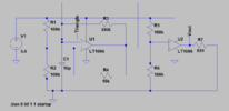
From circuit diagram
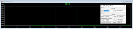
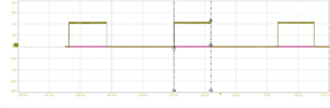
Target : I want to make square wave on Vout (Period =18 sec on :8 sec off: 10 sec)
I have problem when I use scope to measure triangle and Vout , I have followed target. But when I use scope to measure Vout only, time Period and time on reduce. it's not followed target.
I don't understand.
Q: why measure triangle signal and no measure, it's too difference.
* Actual I use op-amp: NJM2904C.
I attached data sheet .
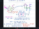
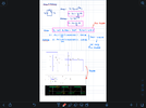
My calculation.
file 1 &2
Please check my calculate is right?
If wrong, I would like to know how to calculate.
Thank you
From circuit diagram
Target : I want to make square wave on Vout (Period =18 sec on :8 sec off: 10 sec)
I have problem when I use scope to measure triangle and Vout , I have followed target. But when I use scope to measure Vout only, time Period and time on reduce. it's not followed target.
I don't understand.
Q: why measure triangle signal and no measure, it's too difference.
* Actual I use op-amp: NJM2904C.
I attached data sheet .
My calculation.
file 1 &2
Please check my calculate is right?
If wrong, I would like to know how to calculate.
Thank you
Attachments
-
 Circuit.png20.9 KB · Views: 308
 -
 2.png384.3 KB · Views: 322
 -
 1.png160.4 KB · Views: 333
 -
NJM2904C_NJM2904CA.pdf776.3 KB · Views: 402
-
NJM2904_E.pdf292.8 KB · Views: 317
-
 Simulate Vout.png16.3 KB · Views: 307
 -
 Actual no Measure tri signal.png112.3 KB · Views: 339
 -
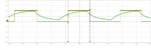 Actual Measure tri signal.png166 KB · Views: 327
 -
Generate square wave .asc2 KB · Views: 352
