Continue to Site

Welcome to our site!

Electro Tech is an online community (with over 170,000 members) who enjoy talking about and building electronic circuits, projects and gadgets. To participate you need to register. Registration is free. Click here to register now.

  • Welcome to our site! Electro Tech is an online community (with over 170,000 members) who enjoy talking about and building electronic circuits, projects and gadgets. To participate you need to register. Registration is free. Click here to register now.

Powered wheelchair motor. How to make it run?

Status
Not open for further replies.

Noober

New Member
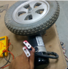
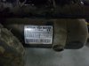
I have two 24V dc motors used in powered wheelchair. Not sure how to do connections to it. Please help. I have attached few pics of the motor and its extension.
This is a part of a project to redesign a powered wheelchair. To start with the project I need to check, what all components work. For that, I am not able to figure out, what to do with the motor.
Following is what all I have tried:
1. Giving 24V to both the white sockets
2. Providing 12V to one and 24V to another and vice versa
3. I tried locking and unlocking the wheels with the lever shown. But nothing helps.

I don't have any prior experience with motors and circuits other than high school knowledge.
 

Attachments

  • motor.PNG
    motor.PNG
    822.3 KB · Views: 480
  • IMG_20160921_234549.jpg
    IMG_20160921_234549.jpg
    2 MB · Views: 548
Last edited:
These are just normal permanent magnet motors. they should run is you connect them to a 12 or 24 volt DC supply. How much current do they draw when you connect 12 or 24 volts to them ? The data plate on the motor is very confusing as it says 24 volts and 3 amps maximum current (72 watts.) and then it says 320 watts.

Les.
 
Another confusing thing: the connector doesn't appear to be polarised, yet the motor plate says 'C.C.W' which (if that denotes counter-clock-wise) suggests that the motor may only work with the correct polarity supply?
 
alec_t the connector doesn't seem to be provided by the manufacturer. Previous wheelchair team might have modified it according to their needs. Maybe the original product had the polarity you expect. Well, I have tried all possible polarity to it, but nothing works.
 
Maybe the "previous wheelchair team" burned the motor out and it is scrap!

Remove the black end cover and inspect the internals of the motor, the commutator and the brushes.
If you are lucky, it may just be that the commutator needs to be cleaned.

JimB
 
Often the reason for CCW/CW on a motor plate will be because it has a threaded shaft to connect such as a flywheel when used in treadmills etc.
If the motor is connected in the opposite direction, obviously the shaft will unscrew.
Max.
 
Often the reason for CCW/CW on a motor plate will be because it has a threaded shaft to connect such as a flywheel when used in treadmills etc.
If the motor is connected in the opposite direction, obviously the shaft will unscrew.
MaxHeadRoom78 you mean the polarity should be in a particular direction only? I do not understand, what do you mean by screwing and unscrewing here
 
As the motors were designed for a wheelchair I would expect them to be reversable. The reason I asked how much current they consumed when connected to a power supply was to get an idea if the motor is open circuit or seized. I was going to ask if the wheels could be rotated by hand but it is possible the gearing is a worm drive and if that was the case then you would not be able to rotate them even if the motor was not seized.

Les.
 
MaxHeadRoom78 you mean the polarity should be in a particular direction only? I do not understand, what do you mean by screwing and unscrewing here
It was referring to the motor plate indication that it indicated as CCW if the motor is limited to this because of a threaded shaft into the Gearbox etc, the direction would have to be changed mechanically. Otherwise a normal DC brushed motor is bi-directional.
Did you do a resistance check of the motor leads and have you inspected the brushes and commutator, the state can often be seen through the brush holder.
Max.
 
I was going to ask if the wheels could be rotated by hand but it is possible the gearing is a worm drive and if that was the case then you would not be able to rotate them even if the motor was not seized.
With a lever, it changes to free state and locked state. That is, maybe, what you are calling gearing up. The circuits seems to be closed because when applied voltage independently then one circuit gives a click sound and other gives a spark when connected.
 
A little bird has whispered in my ear that one side of the supply (probably the -ve side) is connected to the body of the motor, the positive side of the supply connects to one of the two connector pins.

One pin make the motor turn clockwise.
The other pin makes it turn anti-clockwise.

Try it and see what happens.

JimB
 
This https://motiontech.en.taiwantrade.com/product/gearbox-motor-414817.html needs some work.

The motor does have a brake/ The in-line datasheet shows the connections for MTR- and MTR+ and brake.
Your thick wires are the motor and the thinner ones the brake. Both have different ratings.

I don't know what the two things sticking out near the endcap is.

You'll need 4.5 A minimum for the motor and 0.5A to run the brake at 24 V.

JimB: I think the little bird is wrong.
 
Last edited:
With a lever, it changes to free state and locked state. That is, maybe, what you are calling gearing up. The circuits seems to be closed because when applied voltage independently then one circuit gives a click sound and other gives a spark when connected.

The click should be your brake. The spark can be good or bad. What's the capability (AMP wise) of the power supply your using? You could put a say a 5A slow blow fuse in the leads and use a car battery. You'll likely need more than the stated current to start.
 
And 4600 (32:1) means natural RPM and gear ratio?
 
The click will probably be a solenoid brake. Obviously if the brake is on then the motor wont turn even with the correct polarity applied.
It will either be a latching brake, meaning you just need to apply power to move the brake the off position. Or non-latching meaning you would need to constantly apply a current to keep the brake off. (note a solenoid is a current driven device not voltage). I would suspect a latching solenoid so the wheelchair can still be pushed around if the batteries die.
My question would be can you turn the wheel by hand?

For the motor connections, i would Ohm this out rather than just applying power and seeing what happens. If you just apply power you risk burning out the motor.
 
Hi N,
As previously mentioned I think that one of those connectors is a Brake and one for the motor. Try one of your batteries and touch across one of the connectors, if you hear a click then it's the brake, then try the other connector and if the motor turns.....

If you hear a bang and see a spark, then I'm wrong:eek:

I made some Hbridge circuits that will drive them. If the above test works, meaning the motor is ok, I'll post the circuit.
C.
 
Last edited:
Well, the motor works now. It seemed the batteries I was using had some issues. I replaced with another lead acid 12 v batteries for testing. And yes, one pair of wires (thin ones) are that for brakes and another pair is for to get motor running.
 
Status
Not open for further replies.

Latest threads

New Articles From Microcontroller Tips

Back
Top