Continue to Site

Welcome to our site!

Electro Tech is an online community (with over 170,000 members) who enjoy talking about and building electronic circuits, projects and gadgets. To participate you need to register. Registration is free. Click here to register now.

  • Welcome to our site! Electro Tech is an online community (with over 170,000 members) who enjoy talking about and building electronic circuits, projects and gadgets. To participate you need to register. Registration is free. Click here to register now.

Power off time delay circuit

Status
Not open for further replies.

DonMuncy

New Member
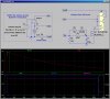
I am working on a circuit to turn off a 12 v relay about 5 or 6 minutes after the power source is removed. I adapted the attached circuit, using a 4700mf capacitor with about 27k resistance. This yields about 1 minute delay. Using an extra 2200mf capacitor in parallel with the larger one only results in about a 15 second increase in the delay time. I tried using more resistors, but raising the resistance by an extra 5K causes the circuit to stop functioning.
Anyone have any ideas about how to increase the delay to 5-6 minutes without increasing the complexity too much. I am a newbie without extensive electronic knowledge.
Thanks for any help.
Don
 

Attachments

  • Timer circuit.doc
    29 KB · Views: 246
You can try replacing the transistor with a FET (e.g. 2n7002). A FET won't drain the power from your capacitor. The corresponding pins of the FET (BJT) are: gate (base), drain (collector) and source (emitter).

Replace the resistor with a wire.

Replace the 1n4004 diode with a 1n4148 in series with a 1k resistor. The 1n4148 has less leakage than the 1n4002, and the 1k resistor is just to limit the current while charging the capacitor.

Replace the capacitor with a 470uF cap in parallel with a 2.2M resistor. These values affect the time the FET is on.
 
after the power source is removed.
If by 'power source' you mean the 12V supply to the relay then regardless of the R and C values the relay will switch off as soon as the power source is removed :(.
 
If by 'power source' you mean the 12V supply to the relay then regardless of the R and C values the relay will switch off as soon as the power source is removed :(.
Unless you store all of the energy required to run the relay and the load in a local capacitor (Bad Idea).

Since the OP implies that a load is being powered by this relay circuit, the OP must really have two inputs available: the vehicle battery +12V, and a circuit which is switched by the ignition key. The key circuit should be used to charge the timing network; the battery circuit supplies the current to both the relay coil and the load.

I am using a similar circuit (without a relay) to automatically power a 2meter transceiver and an APRS unit in my car. When I reach my destination, I want the radio and APRS unit to send out a couple of position reports before the circuit automatically switches off the radio, APRS and its GPS. I will post that circuit when I get to another computer...
 
Pardon me for not being more clear. My knowledge of the terminology is as poor as my electronic knowledge.
This circuit is for the cabin light on my airplane. The light is independent of the master switch (equivalent of the iginition switch on a car). You want to be able to use the light of unloading bags, etc. but if you forget to turn it off, it will run the battery down.
So I set up the circuit with the master switch feeding the left side on the circuit, but with constant power to the relay coil. So when the master switch is turned off, the capacitor charge feeds the transistor until it bleeds down. My problem is getting that bleed down time long enough.
At this time, I am looking for, and having a hard time finding the 2n7002 FET Dougy83 suggested.
Thanks for the help.
Don
 
One problem with affordable high-value capacitors is leakage current, which is variable, making time delays inaccurate. What sort of tolerance can you allow for the '5-6 mins' (I'm guessing ~ 1 min)? Even the venerable 555 timer IC is not good for delays much greater than ~ 1 minute. If you want a consistent delay an alternative approach would be to use a clocked binary counter, or a microprocessor.
 
The accuracy is not much of a concern at all. If I can get it between 4 and 10 minutes, I will be happy.
Don
 
If you're having trouble finding a FET, you can just use your original circuit with an extra NPN transistor set up a darlington pair (as per image below). These two transistors replace the single transistor. The green B, C & E connect to wherever the original transistor's B, C & E were connected.
darlingt.gif

If the storage cap is 220uF and the base resistor is 1M, the on time should be somewhere around 7-10 minutes.
 
...
This circuit is for the cabin light on my airplane. The light is independent of the master switch (equivalent of the iginition switch on a car). You want to be able to use the light of unloading bags, etc. but if you forget to turn it off, it will run the battery down.
So I set up the circuit with the master switch feeding the left side on the circuit, but with constant power to the relay coil. So when the master switch is turned off, the capacitor charge feeds the transistor until it bleeds down. My problem is getting that bleed down time long enough...

Here is a circuit similar to one I am using for another application. The simulation shows a delay of ~360s (6min).

The problem is that if I installed it in my Cessna, I could still run the battery dead because the switch is a slide switch. If the switch gets left in the on position, it will kill the battery. You would have to replace the switch with a momentary spring-return push-button to eliminate the dead battery possibility.

Resistor R4 is there to provide some significant current to keep the switch contacts clean, and provides the discharge path for the timing network. R2 limits the initial inrush current. The delay time is created by C1 discharging to the threshold voltage of M1 (~3V) from one diode drop below the battery voltage, about 2(R1+R4)C1.

Note the traces in the simulation. Green V(sw) shows when the switch is closed. Red V(g) shows M1's gate voltage. Lt. Blue V(d) is M1's drain. Dk. Blue V(load) is the voltage at the dome lamp. Purple is the current through the relay coil.

Note that you do not need to build the stuff in the dashed box. V2 is the human flipping the switch S1. R3 is the existing dome lamp(s). V1 is the battery.

M1 is almost any modern NFet which has an Vds >30V (50V if your airplane is 28V) and an Ron<250mΩ.

btw, for the ones who will notice, there is no, nor does there need to be, a snubber diode across the relay coil.
 

Attachments

  • AutoShutOff.jpg
    AutoShutOff.jpg
    276.5 KB · Views: 250
M1 is almost any modern NFet which has an Vds >30V (50V if your airplane is 28V) and an Ron<250mΩ.
If the master switch is applying 28V to the FET gate won't that need a resistive divider, or a zener, so that the gate max allowable voltage isn't exceeded?
 
If the master switch is applying 28V to the FET gate won't that need a resistive divider, or a zener, so that the gate max allowable voltage isn't exceeded?

Yes. My application is in a 14V car. The Vgs of the old NFET I used is ±20V.

My Cessna is 14V, but newer aircraft use 28V. Don will have to tell us if his application is 14V or 28V?
If 28V, I will modify the timing network to limit the Vgs to <10V, assuming that is the rating of a modern NFET
 
Last edited:
Your really not going to get long RC tye time delays on the order of 5-10 minutes. Long time delays would probably best done with counters or timers. (@alec: like the timer for salty joe). Another possibility is to use a processor, were you can put it to sleep to conserve power.

Your almost looking at building a headlights on for a few minutes after the driver's door is opened sort of circuit.
One vehicle (Chevrolet) actually keeps the ACC terminal powered after the ignition is turned off until the driver's door is opened.

At least you have backup power available.

One thing to look at for a possibility is a magnetic latching relay. A pulse on one coil to turn on and a pulse to turn off.
 
Your really not going to get long RC tye time delays on the order of 5-10 minutes. ...

I just went and grabbed several 330uF to 1000uF 16V or 25V Aluminum electrolytics from my parts storage. I charged them to 12V, disconnected the power supply, and periodically checked the terminal voltage with my DMM (input Z=10megΩ). With the DMM disconnected, the time of self-discharge down to 3V exceeds 10min. If the meter is left connected, the discharge time decreases noticeably. Conclusion: the leakage current is smaller than would be caused by 10megΩ.

This says that in a circuit where the discharge resistance is 470KΩ, the leakage current is small compared to the current through the timing resistor.

I looked at the data sheets on some similar caps at Mouser and Digikey, and their specs imply that the worst-case leakage is about an order of magnitude worse than what I am measuring on my "old" capacitors (I probably have had some of the ones I measured for more than twenty years).

Here is what I would do: buy two 470uF electolytics. Try one in the timing circuit. If the delay is too short, try the other. If the result is the same, use them both in parallel ;)
 
Last edited:
Mike,
I agree that capacitors with enough capacitance to drain slow enough are easy. My problem is the transistor/FET/Darlington pair to use for powering the relay coil and the resistance to use. My original set up worked OK except for the timing. I theorized (with admittedly little knowledge) that raising the resistance high enough to slow down draining the capacitor resulted in not enough voltage getting through to power the transistor. Is this theory likely. I have plenty to learn.
Don
 
In the orginal circuit, the primary discharge path is via the base current of the NPN transistor (worse if it is not a Darlington). Using the NFET, the gate current is just the gate leakage (100nA), which is ~10000 times smaller than the base current of the Darlington. The discharge of the timing capacitor is the electrolytic's self-leakage in parallel with the current through the 470KΩ timing resistor.
 
Don, your idea is close; the problem is that there is not enough current provided to the transistor to turn it on sufficiently. Using the darlington pair in place of the transistor allows you to use a base current 100 or more times smaller, and still operate the relay. It also requires the least modification to your existing/original circuit.
 
Status
Not open for further replies.

Latest threads

Back
Top