Continue to Site

Welcome to our site!

Electro Tech is an online community (with over 170,000 members) who enjoy talking about and building electronic circuits, projects and gadgets. To participate you need to register. Registration is free. Click here to register now.

  • Welcome to our site! Electro Tech is an online community (with over 170,000 members) who enjoy talking about and building electronic circuits, projects and gadgets. To participate you need to register. Registration is free. Click here to register now.

Power factor calculations?

Status
Not open for further replies.
Hello forum,

I have been reading some lectures in this site and I have a question about obtaining the apparent power, true power, reactive power and the power factor of an actual AC circuit.

Basically I am wondering if someone can take a quick look and evaluate or validate that what I am doing is okay.

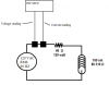
Let's say I have an 120VAC, 60HZ, RL circuit comprising a 60 ohm resistor and a 160 milli-henry coil. This circuit will have two outputs that will connect to a micro controller. Please view attached schematic. One of the ouputs will read the instantaneous current and the other will read the instantaneous voltage (both at the source of the AC circuit). To read the voltage and current, we will build a small circuit that will convert these values to an analog voltage signal so that the micro controller can read them. Therefore, we do not care about *how* the instataneous voltage and current are read... for example purposes, for now, we just know that the micro controller is able to read those values.

So, if we are able to read the instantaneous voltage and current values into the micro controller, then we should be able to calculate the RMS voltage and currents. So for the sake of this example, lets say we are reading an rms current and voltage of:

I = 1.41A
V = 120 VAC

In doing so, I can calculate the total AC impedence by doing:

ZT = 120/1.41A = 85.10 ohms

By having the total impedence, I can calculate the apparent power by doing:

S = I²Z = (1.41²) x 85.10 = 169.256 va

Also, since we are able to read the instantaneous voltage and current of the AC circuit, we are definitely able to detect the pahse angle between the current and voltage. We can the convert this angle to degrees. Assume we have a 45° angle. Refering to the trigonometric triangle, we can then figure out the true and reactive powers by doing:

119.2 watts = 169.256 * cosine 45° <<< true power

119.9 vars = 169.256 * sine 45° <<< reactive power

Also, we can simply calculate the power factor of this circuit by doing:

0.703 = 119.2/169.256

Is what I am doing correct? All feedback is appreciated.

ross
 

Attachments

  • AC_Q.png
    AC_Q.png
    13.7 KB · Views: 230
I need you to think in calculus for a bit.
Known:
Instantaneous peak value
current is sinusoidal
voltage is sinusoidal

How is RMS voltage defined?
from that you'll have two choices

How is power factor defined for sinusoidal voltage and current?
What if the current waveform isn't sinusoidal?
Do you have to consider that?

What is the inout to the a/D?
Doues it have to be protected against spikes?
 
Another way (easy if you have Polar -> Rect and Rect -> Polar coordinate conversion on your calculator.)
Convert the series equivalent circuit to parallel equivalent current. 60 + J60.319 = 120.639 || j120.

60 + j60.319 = 85.114 /_ +45.176 degs. 1/85.0787, change sign of 45.1519 (inverted sign of polar angle) = 0.011754 /_ -45.1519 deg.
Convert back to rect coord. = 0.008289 - j0.008333, invert each component, chg sign of reactive component = 120.6397 || j120.00

Real power = (120vrms)^2 / 120.6397 = 119.364 watts . Reactive power = (120vrms)^2 / j120.0 = 120 VA.

Appearent power = SQRT( (Real power)^2 + (Reactive power)^2) = 169.256 VA.

PF = Real power / appearent power = 119.36 / 169.25 = 0.705
 
Last edited:
One difficulty you might find is that distortion of the waveforms due to harmonics and noise in the mains supply will introduce some quite significant errors into the mathematical process.

It should work fine with a pure harmonic distortion free sine wave voltage source, but you are never going to get that from the mains.

Even trying to measure the phase difference between voltage and current will be difficult when the waveforms have humps and bumps around the zero crossing point, and different harmonic frequencies will have different phase shifts and amplitudes as soon as any reactance is added with a less than unity power factor load.

You are likely to see two very different looking waveforms for voltage and current, not just the same waveform phase and amplitude shifted as you might expect.

Don't underestimate the difficulty of doing this with any useful degree of accuracy in a real world environment.
 
Hello KeepItSimpleStupid,

I have to admit here that I am no expert at this stuff... given the fact that pretty much everything I studied 15 years ago in college is forgotten... since I didn't keep practicing this stuff. You would not believe how quickly someone can forget about this stuff. So I am slowly reviewing my notes the best I can... on my spare time!

>How is RMS voltage defined?

Well, okay, if I am able to read an instantanious voltage into my micro controller, I should then be able to read the peak value right? Therefore 0.707 of that peak value will be my RMS voltage.

>How is power factor defined for sinusoidal voltage and current?
Well, if I have the rms V and I, I can figure out total impedence. With total impedence, I can know the apparent power. If the micro controller can measure the phase angle between V and I, then I can get True power... hence with these two values I can know the power factor.

>What if the current waveform isn't sinusoidal?
>Do you have to consider that?

The wave form will always be sinusoidal.

>What is the inout to the a/D?
>Doues it have to be protected against spikes?

This will be taken care of in phase 2 of the design. I was just looking for some re-assurance that the way I intend to use the calculations to go about this is okay.

Thanks for your reply.
r
 
Last edited:
>What if the current waveform isn't sinusoidal?
>Do you have to consider that?

The wave form will always be sinusoidal.

Reread Warpspeed's post. In an ideal world, it would always be sinusodal. But not necessarily in the real world. After all, the devices that reduce PF can also do a lot of damage to those nice clean, ideal waveforms.
 
>One difficulty you might find is that distortion of the waveforms due to harmonics and noise in the mains supply will introduce some quite significant errors into the mathematical >process.

Humm... I see what you are saying. But then why is it that when I connect my scope to a 120Vac mains of my dwelling via some large resistor, the waveform is crystal clear! If I remember correctly... I did this experiment a few years ago...


>Even trying to measure the phase difference between voltage and current will be difficult when the waveforms have humps and bumps around the zero crossing point, and different >harmonic frequencies will have different phase shifts and amplitudes as soon as any reactance is added with a less than unity power factor load.

Well, in this case, I will have to do some severe sampling of the signals. Perhaps read in 1000 values during an AC cycle and remove all frquency signals that are not 60 HZ.

>You are likely to see two very different looking waveforms for voltage and current, not just the same waveform phase and amplitude shifted as you might expect.

I will have to do some real live testing to actually see this.

However, I just posted this to shed some light on the mathematical process I intend to use based on the V and I instantaneous readings as explained in my innitial post. However, I can see that what you are saying is the probable truth.

Thanks
r
 
Last edited:
Hello RCinFLA,

Okay so we come to the same numbers. In theory! Now as other fellows pointed out.... I will be in for a surprise when testing this out due to noise in the circuit.

Thanks
r
 
Last edited:
Hi carbonzit,

>In an ideal world, it would always be sinusodal. But not necessarily in the real world.

So what is one to do to anticipate this kind of behaviour?

thanks for you reply!
r
 
Yes, non sinusoidal waveforms have funny peak to RMS ratios, and harmonic distortion can shift the zero crossings around, which can make a total nonsense out of phase measurement used to calculate power factor.

SCR/triac controlled loads cause considerable asymmetric waveform distortion with plenty of harmonics generated, and rectifiers flatten the peak voltage quite visibly.

When you start to actually do this, you will very quickly discover that your software calculated values end up being significantly different to what you know the test components actually are.

Not sure what the purpose is, but if it is to be a serious measurement instrument, you are going to have to provide very pure sine wave power yourself to drive the test load, to get any meaningful and repeatable results.
 
Here is a question for you.
If a rectifier is completely open circuit on one half cycle, and has a fixed voltage drop of 0.6 volts on the opposite half cycle, tell me what the calculated impedance of a rectifier? What is it's power factor ?

Definitely not trying to be a smart ass, just trying to point out that ohms law, and generally accepted ac theory cannot always be usefully applied to provide an answer to very highly non linear systems.
 
So how do commercially-available PF meters work? (And as a corollary question, how well do they work?) I'm assuming they're all microprocessor-based.
 
Warpspeed,

i don't know... off the top of my head, without putting much thought into it, 0 and 1 respectively. probably wrong... but been out of it too long for "Gotcha" questions.
So according to you then what is the proper way of doing this?
 
Not all PF meters are microprocessor based, I have one here at home that is truly ancient, a high quality electromechanical instrument built well before the microprocessor era, and it still works fine, and is quite accurate with known loads.

I suppose some type of averaging is used in modern PF meters, I really don't know.

I am only guessing, but suppose it took instantaneous readings of voltage and current, maybe a hundred or more readings per cycle.
You then multiply voltage by current for each instantaneous reading, to get instantaneous power.
Readings would be positive where voltage and current were in phase, and negative when out of phase.
By comparing the in phase power, with out of phase power, you could calculate Watts, VA,s and power factor.

But as above, where mains harmonic distortion is very bad, the readings would be pretty questionable anyway, regardless of how it was measured.
 
Warpspeed,

i don't know... off the top of my head, without putting much thought into it, 0 and 1 respectively. probably wrong... but been out of it too long for "Gotcha" questions.
So according to you then what is the proper way of doing this?

It depends on what the answer is for.
If you want to measure inductance or capacitance (for example), you need to measure the impedance at one frequency, maybe on an inductance bridge, or make it part of an oscillator.
No use feeding some wide band harmonic crap into it and measuring a voltage ???

If you want to know true power, measure the in phase voltage and current, and subtract the out of phase component from it.

As with any measurement, you need to first define what you are actually trying to measure, then do it in a way so as to eliminate as many potential errors as possible.
 
Hello RCinFLA,

Okay so we come to the same numbers. In theory! Now as other fellows pointed out.... I will be in for a surprise when testing this out due to noise in the circuit.

Thanks
r

There won't be a problem with noise. This is pretty real world when dealing with inductive motors which is the dominate cause of poor power factor to power companies. If you look at utility poles you will sometimes find a parallel stacking of square boxes with two insulator sticking up at top of each box. These are capacitors put on the power line line to compensate for high inductive loads (air conditioners, factory motors).

The other guys are trying to drag you into non-sinewave analysis which you may not have the math for yet. Things like simple rectifier-filter based power supplies only conduct current at the peak of the sinewave to recharge filter cap. These have relatively short current pulses. In this cases the original definition of power factor must change a bit but the effect is similar, not providing the most average AC power for minimal distribution wire loss.
 
Last edited:
Measuring true RMS power in the presence of distortion or reactive current is not complicated. If you multiply the instantaneous voltage by the instantaneous current (including sign for both) for many samples (sample frequency high enough to resolve any waveform noise or distortion) over the waveform period and average the results, you will get the true RMS power independent of distortion or power factor.
 
>over the waveform period and average the results, you will get the true RMS power independent of distortion or power factor.

That's even easier than what I am doing.

Thanks crutschow
 
Hi Warpspeed,

>If you want to measure inductance or capacitance (for example), you ...

Nope, I don't want to measure xl or xc. I need total power readings only. va, watts and vars... that's all and nothing more. It's an AC circuit!!! I am not going to go around to every xl and xc loads and logging down on a peice of paper their milli-henrys and ufarads. I simply want totals so I can do my cosine of the angle...to get my powers as shown in my innitial post.

>If you want to know true power, measure the in phase voltage and current, and subtract the out of phase component from it.

But isn't that what I am doing. Anyways... our pet peave with all of this was that it will be difficult to read clean instataneous V and I values into my micro controller. This is the issue here.

r
 
Last edited:
.................
Anyways... our pet peave with all of this was that it will be difficult to read clean instantaneous V and I values into my micro controller. This is the issue here.
If you analog filter the voltage and current waveforms to remove noise components about the Nyquist frequency (1/2 the sample frequency) then you should be able to measure clean instantaneous values of both with an A/D converter (either an external A/D or one built in to the micro controller). Of course you will need to measure both positive and negative values and multiply them together with their sign.
 
Status
Not open for further replies.

Latest threads

New Articles From Microcontroller Tips

Back
Top