Continue to Site

Welcome to our site!

Electro Tech is an online community (with over 170,000 members) who enjoy talking about and building electronic circuits, projects and gadgets. To participate you need to register. Registration is free. Click here to register now.

  • Welcome to our site! Electro Tech is an online community (with over 170,000 members) who enjoy talking about and building electronic circuits, projects and gadgets. To participate you need to register. Registration is free. Click here to register now.
Status
Not open for further replies.

blueboy

New Member
Hello everyone,
I am new to filter design and I want to design an audio equalizer. I used Sallen key topology design calculator from:
https://www.changpuak.ch/electronics/Sallen_Key_Bandpass_light.php

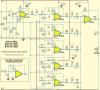
I designed five band bandpass filter having simple low pass and high pass for initial and final bands.... The problem is that when i use a summing amplifier to control gain and get output, i get very poor graph for frequency response with depressions which i think is due to phase shift of different bands interfering with each other.... I summed the individual gain of bands with respect to frequency and i got fairly smooth response.....

is there any way i can remove this phase shift??? or get normal output??


Please Help!!
https://i.imgur.com/UMwEvlX.png
 

Attachments

  • Draft4.asc
    11.9 KB · Views: 233
I did a search for 5 band equalizer:
Note that each filter has the same number of op-amps/ same type of filter/ same .....
I do not know you answer!
It is strange that you have filters with 1, 2 or 3 op-amps.
There are also filters with a RC or no RC on the output. I only see a small difference. (8%)
I think you want each filter to be built the same way.
I do not have time to build up this circuit and see what is different.


upload_2017-12-16_8-15-45.png
 

Attachments

  • upload_2017-12-16_8-16-12.png
    upload_2017-12-16_8-16-12.png
    518 KB · Views: 260
Highpass-lowpass Sallen-Key filters are not used in audio equalizer circuits. Multiple Feedback Bandpass filters as shown or Baxandall filters or simulated inductor circuits are used instead.
Here is a classic equalizer circuit using Baxandall filters. https://www.circuitlib.com/index.ph...9-audio-graphic-equalizer/category_pathway-28

Here is an article from Texas Instruments.
https://www.ti.com/lit/an/slyt134/slyt134.pdf

I think your problem is caused by the 2nd-order filters have 180 degrees of phase shift that cause cancellation when added out-of-phase.
 
Since none of the filters in the original schematic are adjustable, what are you "equalizing"?

ak
 
If you dont mind a load of op amps I've had some success with gyrator filter eq's.
Fig 5:
https://ethanwiner.com/spectrum.html
They say a gyrator is a square root of a transformer.
High Q circuits unless carefully designed can cause phase shift and ringing, which basically will make your sound 'orrible.
 
Last edited:
Gyrator was the word I was looking for. It is a synthetic inductor.

I never used an equalizer or tone controls on my home audio system because it sounds perfect without them. My new hearing aids do equalization to make my old hearing sound young again.
I just finished playing a tiny portable speaker given to me by my son. Its attempt at playing bass frequencies is a joke but I see its drone cone vibrating and causing the entire speaker to vibrate. It sounds good up close and far away its midrange and highs are very loud for its small size.
 
I did a search for 5 band equalizer:
Note that each filter has the same number of op-amps/ same type of filter/ same .....
I do not know you answer!
It is strange that you have filters with 1, 2 or 3 op-amps.
There are also filters with a RC or no RC on the output. I only see a small difference. (8%)
I think you want each filter to be built the same way.
I do not have time to build up this circuit and see what is different.


View attachment 109698
Thanks ronsimpson! I will try this one.

Highpass-lowpass Sallen-Key filters are not used in audio equalizer circuits. Multiple Feedback Bandpass filters as shown or Baxandall filters or simulated inductor circuits are used instead.
Here is a classic equalizer circuit using Baxandall filters. https://www.circuitlib.com/index.ph...9-audio-graphic-equalizer/category_pathway-28

Here is an article from Texas Instruments.
https://www.ti.com/lit/an/slyt134/slyt134.pdf

I think your problem is caused by the 2nd-order filters have 180 degrees of phase shift that cause cancellation when added out-of-phase.

yeah, the problem is cancellation due to phase shift.

OK, I am changing to narrow band bandpass filters.. lets see the results.
 
Just curious. What about chebyshev bandpass or butterworth bandpass filters? will they be any good in terms of equalized audio output?
 
A Chebyshev filter can have a steeper cutoff slope adjacent to the corner frequency, but it also has significantly greater phase shift (distortion?).
 
Ok, I simulated the circuit.
I did a search for 5 band equalizer:
Note that each filter has the same number of op-amps/ same type of filter/ same .....
I do not know you answer!
It is strange that you have filters with 1, 2 or 3 op-amps.
There are also filters with a RC or no RC on the output. I only see a small difference. (8%)
I think you want each filter to be built the same way.
I do not have time to build up this circuit and see what is different.


View attachment 109698
output is still showing peaks. It is also multiple feedback so what is the problem?
Graph: https://imgur.com/EehZVFN
Circuit: https://imgur.com/swOEp3B

Had to do on PSpice
 
ok, The problem is solved by adjusting Q-factor to produce fairly smooth frequency response.


Thanks very much guys!
 
The article from Texas Instruments I posted says an audio equalizer circuit needs filters with a low Q and they recommend gyrators. Many equalizer circuits use Baxandall "tone control" filters that are single order (low Q) with maximum phase shift low enough to be added without cancellation. Some circuits have one opamp with many filters. Other circuits use an opamp for each filter.
 
The article from Texas Instruments I posted says an audio equalizer circuit needs filters with a low Q and they recommend gyrators. Many equalizer circuits use Baxandall "tone control" filters that are single order (low Q) with maximum phase shift low enough to be added without cancellation. Some circuits have one opamp with many filters. Other circuits use an opamp for each filter.
Thanks for the info!

I looked it up and it seems to have a pretty nice response. I will simulate it to check if it is a better choice
 
Status
Not open for further replies.

Latest threads

New Articles From Microcontroller Tips

Back
Top