Continue to Site

Welcome to our site!

Electro Tech is an online community (with over 170,000 members) who enjoy talking about and building electronic circuits, projects and gadgets. To participate you need to register. Registration is free. Click here to register now.

  • Welcome to our site! Electro Tech is an online community (with over 170,000 members) who enjoy talking about and building electronic circuits, projects and gadgets. To participate you need to register. Registration is free. Click here to register now.

PeeWee Inverter

Status
Not open for further replies.

Tedfred

New Member
Hi guys
I am looking to put to gather a very low price photovoltaic solar system. The
project has two parts.
1. The solar panel or solar cells.
2. The inverter. The inverters will output ac or dc.
I am working on two small inverters. One has AC output, the other has DC
output.

Individual photovoltaic solar cells can be had for about $1.00 each in lots of 100 or so. Check out the internet for best deal. The cells that I looked at were 0.5 volts at 3 amps in bright sun light. As a start up question, can you convert one single solar cell 0.5 voltage to 2 volts so as to charge a 1.5 volt C cell (battery). Most transistors don't rely conduct very well under 1 volt. So go mechanical using a paniconic .5 volt relay, 2.5 volt ct power tranformat(turned backwards) and a diode might work. However the cost is more than the cost of buying 4 solar cells. 4 cells generates 2 volts 3 amp in bright sun light, which can over charge small batteries so a regulator is needed. More later or not?

Question 2: Can 4 solar cells or more to run and inverter to get 110 volt AC at a few watts. Even 20 watts can run light, radio, razor, phone and other small stuff. But the inverter has a high cost ratio to the solar cells. More later or not?

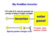
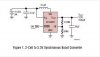
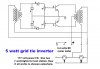
Question 3: Can a peewee inverter be built for under $150.00 to feed energy
back into the grid. How much for a 10 watt inverter, 100 watt inverter, 1000
watt inverter.

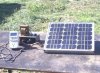
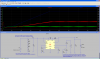
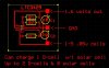
I have a few diagrams and pictures from projects above. I will be uploading them to the internet at some point. Sum stuff sort of works. The grid tie
PeeWee inverter does not work. Yet!
 
How are you going to measure the savings from your 10W grid tie? If your energy is available continuously (geothermal?) it can send no more than 25 cents a week back to the utility.
 
DC-DC voltage conversation at such low voltages is extremely low efficiency, you're better off using more solar cells in series to get a more appropriate voltage to work with directly and then regulate it from there.
 
DC-DC inverter & grid tie inveter

Hi all ..
As to the measuring power from the inverter:
I am a sort of a backyard build it person. So number one object is to get thing working,(and the peewee invert is not up and running yet.) and then add needed accessory to the project. However many people ask for some kind of power indicator. A picture may be worth a thousand words. So here is a picture on one or many possibility. As you can see I a use three parts 1.the panel. 2. The (the not working inverter) and 3.A kill-a-watt meter which sells for about $30.00. I could use a shunt resistor in the solar panel circuit or in the grid tie circuit. Then use a volt/amp meter to read the current flow that circuit. This would give a fare indication of power delivered.

As to the 0.5 volt DC-DC inverter.
I built one long time a go using a relay as a vibrator and a 2.5 filament transformer, just to see if I could. The prototype had a parts cost or about $60.00. and that did not include all of the wrong parts that I bought or the time spent. The output with its big time losses was only a few milliwatts out. (NOT VERY GOOD) but..... As it turns out Texas instrument as a I.C. chip part no. TPS61200 that runs on 0.5 volts solar cell. And coverts it to about 3 volts at 1 watt. And sales for 1.20 in lots of 1000. $49.00 for aboard ready to. This is far better then what I have. But still may not be cost efective. So why is Texas instrument making this part?

O.K. back to my PeeWee inverter. I will be up loading much of this stuff on to my site. I will post the name of my site latter when I fine out if it is safe to post it here.
 

Attachments

  • solar_pan072.jpg
    solar_pan072.jpg
    158.9 KB · Views: 975
PeeWee Inverter Switch

What is the switch I see pictured? Is it an On / Off switch? If so, why is it necessary?
 
Its entirely possible to build a 10 watt grid tie inverter but for all practical purposes the rate of return Vs how long it would have to run will be very very long.
Small transformers have the lowest efficiency of any common transformer design. Your 10 watt output could likely require over 40 watts or more at the input simply due to switching losses and transformer step up losses.
Being that small of output you wont need much for line filtering or safety interlock circuitry though. A basic input voltage sensing circuit to tell it when to connect and disconnect would suffice.
Its still recommended to have the full safety and line monitoring circuitry but at that low of power adding another watt of internal load actually adds up.
And really if anyone has concerns about a 10 watt GTI islanding the neighborhood... Really? seriously, Really? :confused:

As far as providing an independent power source for phone charging or other small load 120 VAC powered things it would be far more cost effective to just go and buy one of those mini 35 watt inverters that plugs directly into an automotive cigarette lighter socket. I have seen them on sale locally for about $15 before.:)

Just use a good several amp hour 12 volt battery that gets recharged off of a string of solar panels set up in series to provide a high enough voltage to charge the battery.
Assuming $15 for the inverter, $20 for a good surplus UPS battery and about $25 in misc surplus parts for the GTI it might be possible to make the system you are thinking about for around $100 including 30 - 40 of those $1 solar panels. ;)
 
Back to the drafting board.

Hi you-all again:
Thanks you-all for all of the good info. Some of this stuff I should know, but I still appreciate the input.

As to the no/off switch: lights, T.V. radios have no/off switches. This is an inverter!! it's switch goes OFF/NO and not ON/OFF. he he

As to the 10 watts:
I only thought that I would start with a scaled down inverter to save the cost on making the prototype. A 250-1000 watts inverter would be more practical. I could not in all honesty post the newer inverter mess that I an playing with. Here is why, with the rest of the story in short. My friend Paul and I were having a talk about making a simple “Plug In” grid tie inverter. The optimum word is "plug in" Having way to many wine coolers, I agreed that I could whip out a working model in less than a week, no problem. "WHAT WAS I THINKING!! Below is the proposed block diagram of what I should do. I now know that there is so many holes in this idea, that even Swiss cheese would disappear. There is the electrical receptacle gender defugalty. With a standard 110 volt plug, on a bright sunny day this inverter (if it worked) would have would have a shocking 110 volts on its prongs. So for safety we need to change the cord to a female cap cord instead. Now we can’t plug the female plug into the female receptacle. So a special 110 volt gender changer cord will need to be made up. See picture below. None of this idea is safe.
NOTE DOT MAKE GENGER CORDS LIKE BE LOW. THERE ARE DANGEROUS !!
I have a few ideas that might work… but I thought I might put this out here for you-all.
Also out of sync inverter can generate as much as 220 volt differential on the plugs but that is another story.
 

Attachments

  • inverter2.jpg
    inverter2.jpg
    52.8 KB · Views: 868
It is possible to make relatively efficient and low cost inverters in the 10W-100W range using a high frequency switching setup (the usefulness of such a device is another question). Of course, keyword being 'relative'. They don't start getting cheap until you go up to 250W-500W which is about the range at which they become inefficient and a traditional transformer based setup starts to make more sense.

Making a 12V to 170V DC-DC converter with 85% - 90% efficiency isn't that tough given you have good magnetics. Making that inverter a GTI is where it gets tough, complicated, and expensive.

I've been playing with getting a 250W high frequency switching GTI setup working efficiently in spice simulation and the damn schematic keeps growing and growing... About half of it has nothing to do with transferring power, and just making the damn thing run synchronized to the grid.

Long story short: if your end goal is a 1kW inverter, don't bother with looking at a 10W or 100W design as the setup for an efficient 100W device is very different than that for an efficient 1kW device.
 
Hi guys :
As to the unsafe plug.
I guess no one cares about the mismatched receptacle gender above and it’s dangerous 110 AC volts on the prongs. I guess that my peewee inverter can’t be used safely in a standard 110 volt ac outlet.

I am now going back to the drafting board. (There will be a working peewee inverter of some kind if I have anything to do with it) I think that there is a strong need for working DC-DC, DC-AC inverter wiring diagram that are easy to get to. All on the same site. I an in the process of gathering basic inverter diagrams and putting then on a site that I have. This task can be very time consuming, so it would be of great help if any one could point me to complete working inverter diagrams. Old or new large or small. These diagrams well be made available to everyone. If you google “peewee inverter” you will find my page. There is no sales, just free information.
 
Last edited by a moderator:
1.2 watt D-cell charger using 1 3"x6"solar cell diagram

OK every one:
You guys out there are eating me alive for something that I that am not doing. I make a Great Big type-0-… The word that I meant to type, was FREE not FEE. I could have not picked a worse word to miss spell! I get the message. Nobody is interested is placing inverter semantic all in one easy to get places. Lest ways not on any of my sites. Ok fine a simple “no thank you” would be all that was required. For those that have been on any of my sites, they know that it is all give and no take. The site is just as I stated above (except for the type-0) So before chastising me be sure you get right.

I would like to please get back to my project(s). I have been working on a very small inverter that uses about $20.00 or less in parts. It Runs on a 3”x6” single 0.5 volt solar cell and generates about 2 volts at about .675 amps. The inverter can then charge flash batteries or whatever. I will be glade to share the semantic and my findings with everyone as soon as I get it dialed in. This inverter may be about %80 efficient. But this is only a guess. Below is a slight variation of my project.
 

Attachments

  • grnpowp1.jpeg
    grnpowp1.jpeg
    22 KB · Views: 948
Hi Tedfred,
Thank you for clearing the fee/free confusion up, I fixed your thread and deleted the off topic threads about it. hopefully other members can now stay on topic for this thread as all the confusion has been sorted out.

Regards Bryan
 
Cross one off the to-do list

Edit: Looks like my earlier post didn't make it here... So here goes again...

I don't think the setup in your schematic will work very well since there is nothing keeping the PV cell from being pulled to very low voltage (making it produce very little power).

Unfortunately you cannot just hookup the feedback of the controller to the PV side to regulate the PV voltage since the circuits for input vs output feedback regulation work backwards, ie:

For input feedback, you want to pull less current when the voltage drops.
For output feedback, you want to pull more current when the voltage drops.

If you use a chip that gives you full access to the error amplifiers, you can setup the feedback to work whatever way you like, including a proper input feedback. Unforunately, most companies don't make such chips and the only ones I can think of off the top of my head are the super-old and inefficient TL594's (https://focus.ti.com/docs/prod/folders/print/tl594.html).

Alternatively, you can use a setup like a transistor inverter to invert the feedback chain of the controller.


Well, I did what I suggested earlier. Attached is a spice shot and source for LTSpice. You'll have to change things around a bit if you actually want to build something, but I think it's good enough for a proof of concept.
 

Attachments

  • pv charger.png
    pv charger.png
    110.6 KB · Views: 743
  • pv charger.asc
    3.7 KB · Views: 487
Last edited:
I am not crossing this off my to do list until I am happy with it. I know that I could just go buy a box of “copper-top” batteries or buy a D-cell charger for $30.00 $40.00 dollars. The point being that one should be able to build a simple one for under $20.00 if they want to. I have one that works (see diagram above), but it is not with out some problems. It cost be $50.00 dollar and that is too much to be profitable. (see photo below) I look at the pv_charger.asc above. Here is what I found. The simulator showed that the circuit petered out below about .9 volts in. Mine petered in about .3 volts. So mine was better with a sing solar cell. But I guess I am nit picking. It would be for better off to just though a second solar cell in to the system and be done with it. Will, after much time researching things, I found similar but maybe a better part. The part number is LTC3429 and is in the Ltspice simulator (I give credit to TodX for this find). All though not the best choice electrical, it dose have one something better. It only has 6 pin outs and they may be far enough apart to be able to breadboard this part simpl
 
The transistor setup above should work on any smps chip. I just used that one because it had similar properties to what you were looking for and there was already a spice model for it with LTspice, so I didn't have to deal with importing one. But I'm sure there are better chips out there.

Running off of one cell makes it rather challenging to make something that works reliably if you use a transistor setup like the one above. To use a bipolar transistor you need at least 0.7V for the gate forward bias. And you'll want some operating room above that. You'll need at least 2 cells to make that work =/

Alternatively you can look at using something like a jfet instead of the bipolar transistor. That should be able to work below 0.7V.

But you will need some kind of input feedback or you'll most likely be running the cell at a fraction of it's possible power output.

You can see why this is in the typical solar cell I-V/Power graph in this post.
 
Anyone out there have any simple suggestion on how to solder small IC parts to a PC board on a one time bass. The pins on a LTC3429 are about 1 MM apart.

After looking around for way to many 'boost Buck-Boost Regulator' IC chips, I have decided on using the LTC3429 IC.( if it can be simply soldered to a PC board) It is cheap and may be easier to solder, only 6 pins. All parts well under $10.00 not counting the p.c. board. I an ok with bread boarding the first one. A real Board can be make in lots of 10 for about $100.00. I am calling this project peewee-1 and is capable of delivering one or two watts and will charge 1 or 2 D-cell flash light batteries. (maybe Ipods and other stuff) It looks like 8 solar cells are max limit for this chip. Below is a possible PC board and working schematic.

More power Scotty:
Back to page 1 and the grid tie inverter. Peewee-2 would be a 12volt DC to 110volts AC inverter. But you can buy them on the internet for $20.00 and up. However to be complete, I plan too make a non synchronous version (peewee-2) and a synchronous version.(peewee-3) The two will have a similar parts list and construction. I will be ignoring the cost factor until I get things running. I have been messing around with the peewee-3 version for a while and as stated on page 1, I is not working yet. I am getting tired of replacing blown out fuses on my test station on failed tests. I now using two light bulb, a 40 watt and a 150 watt as part or the test station. Now the 150 watt bulb lights if I burn out a transistor or two in the peewee-3 project. I will be glade to post the semantic on the test station, peewee-2, or peewee-3 if any one is interested.
 

Attachments

  • inverter_bd.jpg
    inverter_bd.jpg
    60.3 KB · Views: 583
  • inverter_ct.jpg
    inverter_ct.jpg
    13.5 KB · Views: 581
There are plenty of tutorials on SMD soldering techniques. If you already can do quality work with through hole there's nothing to be afraid of.

As with any new skill, practice on a dummy before hitting the $$ parts. Find willing victim such as a TV or VCR on the curb or garage sale.
 
Seeing as how we live in a throw away society nowdays just ask family and friends to save any home electronics that have stopped working within the last year or two. Use a bulk heat gone to blast the SMD parts off the board into a bucket and have a wack and soldering them back onto something =) You can practice on the same test pad many times.
 
Simple 5 watt grid tie inverter

I am sell working on these tiny chips. Looks like it is going to take me some time be for I get it. How ever on a larger scale I put together a very simple 5 watt grid tie inverter. See schematic below. This one sort of works I think. The input voltage is 3 to 4 volts DC. The 2 potentiometers are link together so as to turn on single shaft. The adjustment is very critical. If the DC volt in change, you will have to tweak the potentiometer. This is the short version on how I start it up. DC volts at 0 volts. Potentiometer turn to zero, full ccw.
Turn on the 110 volts AC. Lamps 1 & 2 will light up dimly. Next turn up the DC to 3 volts. Now start turning up the potentiometer slowly. If the sync transformer ( one on the left) is wired in phase, lamp 2 will brighten and light 1 will dim. Stop turning when lamp 1 goes clear out. I now jumper lamp 1 with a amp meter to read current. Next unscrew lamp 2 to in current reading on amp meter. If lamp 1 lights up full brightness and no lamp 2, look for a short some where in the inverter. (check transistor for shorts) If lamp 1 gets brighter, the one of the transformer winding is hook up in reverse. More later.

Here is the question. The current measured from the amp probe, is it currrent
going into the grid or is the current flowing back the other way. I can tell you that if the secondary winding is disconnected from everything and a lamp place across it will light up. Would an oscilloscope give me AC current direction. IF so how.
 

Attachments

  • inverter7.jpg
    inverter7.jpg
    56.2 KB · Views: 843
Which kind of answers the question "is it generating current or consuming it"?
;)

As for testing the current direction it is quite easy. Put a current sense resistor in series with the active lead, then just measure the AC RMS voltage from each side of the resistor to neutral, the higher AC voltage wavform is the "source" and will be feeding current through the resistor to the other.

I'm not sure the simple circuit will work... Won't there be problems from the phase lag of the transformers adding together? And what stops it from zapping someone if the mains is disconnected?
 
Status
Not open for further replies.

Latest threads

New Articles From Microcontroller Tips

Back
Top