Continue to Site

Welcome to our site!

Electro Tech is an online community (with over 170,000 members) who enjoy talking about and building electronic circuits, projects and gadgets. To participate you need to register. Registration is free. Click here to register now.

  • Welcome to our site! Electro Tech is an online community (with over 170,000 members) who enjoy talking about and building electronic circuits, projects and gadgets. To participate you need to register. Registration is free. Click here to register now.

Parallel port driving ADC problems..

Status
Not open for further replies.

saiello

New Member
Hi All,
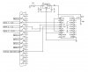
I posted a while back on the use of the PC parallel port to drive a DAC and ADC as an interface to a variety of sensors/PWM's. I breadboarded a circuit and have written the software in VB6. The DAC chip performed perfectly first time out ( not what I was expecting! ), I can specify a voltage by moving a slider in the software and instantly get a corresponding voltage output. :D The ADC uses the same SPI interface and is driven in a similar way to the DAC. Although I can get the ADC to respond and return a voltage, all I get back are random spurious readings even when trying to read the internal test reference voltage. I've been through the datasheet with a fine toothcomb but cannot find anything that could be causing the problem, at least from an electronics perspective. I've checked the software thoroughly, slowing the timings right down to tenths of a second, making sure that everything is synchronised in terms of input clock pulses and data and the converted output data, but it's got me stumped. :confused: If anyone has experience of the TLC2543 ADC or even of driving this IC through the parallel port I'd be greatful for any input! :) I've attached a schematic showing the breadboard setup.

Thanks!
 

Attachments

  • ADC.jpg
    ADC.jpg
    39.3 KB · Views: 269
Perhaps you should try to make some simple software to start with. You know; "Barebones". When i make software (highend), i like to make simple little bits of code just to get things to work, and then reprogram it to work in the "big picture". If you are sure that your code is right, then i would also try some different circuits. Maybe some LEDs on the output lines of the ADC? That way you can see what is happening?

I have never used an ADC or DAC before, so maybe this is dumb advice, but someone somewhere could use it. ;)

Good luck. If you get a chance, maybe you could post some source? :)
 
Hi!
Thanks for the reply! :) The DAC I'm using ( TLC5628 ) and the software worked great first time out. The ADC (TLC2543) uses similar VB code and the structure of the sequence of instructions sent is also very similar. I'll re-write the code to explicitly step through the 36 byte instruction sequence byte by byte as it it sent to the ADC so I can check the lines with a voltmeter. I've checked some application notes on the Texas Instruments website specifically for the 2543 and the last example shows use of a microcontroller directly interfaced with the 2543 and using purely software to drive the SPI interface ( i.e. Chip Select, I/O clock, data in and data out lines ), so logically no reason why a PC couldn't do the same.:D Once I write the test code I'll post it so that you ( or anyone else that's interested! ), can see the exact information the ADC is getting and tie this in with the information contained in the datasheet.

Thanks!
 
Hi,
I've written the 'bare-bones' code to drive the ADC. I've attached the code and also the datasheet for the TLC2543. Still no joy, I'm stumped..! :confused:

Cheers,
Salvatore.
 

Attachments

  • ADC.txt
    8.5 KB · Views: 235
  • tlc2543.pdf
    705 KB · Views: 407
hi salvatore,
Looked thru your VB code fragment, unable to run it as its not complete.

Perhaps a simple question, are using Windows XP, if so you will require a *.dll
in your Windows/System directory. I use 'inpout32.dll'.

I have written a parallel port test program using VB5, if it would help let me know and I will post it.
 
Hi,
I'm using XP Pro and the same inpout32.dll. I've amended the code ( attached ) to include the declarations for the input/output functions so it should now work as is. Incidentally, I had changed the DB25 pin assignments slightly to accomodate the test code and as such I attach the resulting revised schematic. I can drive the TLC5628 DAC in a similar fashion and it works sweet, it's the TLC2543 ADC that's giving me headaches.! :( I can certainly get results back from the ADC but they are totally spurious readings! I thought at first it might be an input/ouput synchronisation issue, but I've revisted the code many times and can't see any problem. I also suspected that I might not be driving the ADC according to the datasheet, but again can't find anything that suggests I'm doing something wrong. If you've got some software to test I'd certainly appreciate trying it out!

Thanks,
Salvatore.
 

Attachments

  • ADC.jpg
    ADC.jpg
    48.1 KB · Views: 204
  • ADC.txt
    8.8 KB · Views: 270
hi salvatore,

The *.zip includes the source code in VB5, also a *.exe file.

The purpose of the program is just to exercise the parallel port I/O.

I will re-try your code, I will have to simulate, in some way, the ADC ic.

If I get a result I will get back to you.
 
Last edited:
Hi Eric,
Thanks for the code! I sent an instruction sequence to the ADC by toggling bit 1 ( DATA 1, Pin 3 ) for the CLK and monitored the output bit 6 ( STATUS 6, Pin 10 ). After running through a number of 12-bit instruction sequences and writing down the output results, I found I was still getting random results.
I'm going to have another hard look at the datasheet to see if I've missed something.

Thanks again,
Salvatore.
 
hi Salvatore,
Look at this, in your coding.
ADCResult(0) = Inp(STATUS) ' Read STATUS port and store MSB

'D9
ADCResult(2) = Inp(STATUS)
Out DATA, StringToBits("00000100")
Out DATA, StringToBits("00000110")
Out DATA, StringToBits("00000100")
ADCResult(0) = Inp(STATUS)
;****

Is this statement supposed to be here??, you are changing the state of the MSB to the state of B9

I have inserted some dummy values into your ReadSubr and it gives the correct results. A problem occurs in D9 read block.
To test I changed ADCResult(0) to 64' Inp(STATUS)
and ADCResult(1 thru 11) to 32' Inp(STATUS), and deleted the *** line.

Thus gives a final result value of 2048, which is correct.

I expect you know that your code is not optimised and could be reduced in size and also faster.

Regards
 
hi,
Looking at the ADC setup routine in 'ReadVoltage', if I am reading page #14 of the datasheet correctly, the setup is addressing AIN3. You appear to be using AIN0 as a 2.5Vref test value?.

Page #14 also states its an 8 bit function select byte, you are adding, 4 padout bits?

On page #12 of the datasheet, 'Principles of Operation' it again states its an 8 bit control data stream.

On page #9 it states that the data I/O is simultaneous, you are addressing and reading sequentially?

You appreciate that unless I have a device to test with your program, I have to take all my information from the datasheet.

The way I read the datasheet, you are not controlling it in the way it describes.

Regards.
 
Hi Eric,
Thank you for your patience! You are right in pointing out the mistake in the code I posted. In actual fact the code itself does not contain this error, it was introduced after cutting and pasting the code into Notepad and making a few adjustments to pretty it up..! Sorry! :rolleyes: 
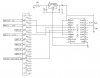
To keep things as simple as possible, I have attached a shorter, clearer version of the code that uses AIN0 on which I have 2.5V. This equates to an actual instruction sequence of all 0's, so all I am effectively doing is sending CLK pulses to the ADC. On every call to ReadVoltage(), I have also added a bit of code to initialise the ADC according to the datasheet by taking CS temporarily HI and then LO again and then waiting a bit for the ADC to settle down.
In answer to your query about the 8-bit function select byte, the ADC allows 3 choices in terms of length of the instruction sent to it depending on the type of serial communications mechanism you are using, 8-bit, 12-bit( recommended as the ADC has a 12-bit resolution), and 16-bit ( see page #15 - Principles of Operation - data output length). The function select byte is 8 bits which in my case has to be padded to 12 bits. There is a timing diagram on page #9, figure 9 which is the control scenario I am trying to implement.
In answer to your other query about the ADC being simultaneous, yes it has been designed this way for fast operation. As you are sending an instruction, the result of the previous conversion is shifted out, so the desired result lags behind by one instruction sequence. In my code, I send the instruction twice, the first is the 'real' instruction, the second as a 'dummy' to get access to the result. Although not in the datasheet, the method I'm using is actually recommended in the manufacturers application notes if all you are interested in is 'one-shot' conversions. If you are trying to convert a fast continuously varying signal then the simultaneous method is obviously recommended for speed.
I've tested the attached code and am still getting spurious results as before.:( Not entirely sure where to go from here...

Thanks,
Salvatore.
 

Attachments

  • ADC2.txt
    5.9 KB · Views: 196
Last edited:
When I was working with ATMega16's ADCs I faced a similar kind of problem. The output was very unstable. Later I found out that in the breadboard the voltage of the ground rail was 150mV. May be yours is the same problem.
 
hi salvatore,
Try this code, add to the Form, 1 sec Timer and a Text1 box.
This works using the parallel port and a project board. The ADC is simulated.

Code:
Option Explicit
Dim DATA
Dim STATUS
Dim ADCValue As Single
Dim Ary(12) ' for precalculated power values

Private Sub Form_Load()

DATA = &H378 ' LPT1 port address
STATUS = &H379 'STATUS port address
MakeAry

End Sub

Private Sub MyRead()
Dim Rd, iADCValue, V As Integer
Dim t As Long
'this routine,selects ADC0, 12 bit data, msb 1st, binary, NOT using /CS as Page #9
'remember to allow for EOC time out

        For Rd = 0 To 11
        V = Inp(STATUS) And 64
        If V = 0 Then GoTo skip1
        
        iADCValue = iADCValue + Ary(Rd)
skip1:
        Out DATA, 0 'ck=lo, cs=lo, dta=lo
        Out DATA, 2 'ck=hi, cs=lo, dta=lo
        Out DATA, 0 'ck=lo, cs=lo, dta=lo
        Next Rd
            
    ADCValue = iADCValue

End Sub

Private Sub MakeAry()
Dim z As Integer

For z = 11 To 0 Step -1
Ary(z) = 2 ^ z
Next z

End Sub

Private Sub Timer1_Timer()
MyRead

Text1.SelText = "Decimal= " & ADCValue & "         Vadc= " & (ADCValue / 4095) * 5 & vbCrLf
End Sub

Read the comments.

I'll look thru your latest *.zip

Regards
 
Hi Eric,
Neat bit of code! :D I tried it and it does give me more stable results, either 0V or a value around 4.9V, but not the value of the input to AIN0 which is still 2.5V. I amended my own code to make it more streamline and I get the same results. What I did find interesting is that if I place any piece of code anywhere in the For..Next loop I start to get completely random results again! E.g.

For Rd = 0 To 11

' Add any code here.. e.g. Wait 0.001

V = Inp(STATUS) And 64
If V = 0 Then GoTo skip1

iADCValue = iADCValue + Ary(Rd)
skip1:

' ..or here.. e.g. DoEvents

Out DATA, 0 'ck=lo, cs=lo, dta=lo
Out DATA, 2 'ck=hi, cs=lo, dta=lo
Out DATA, 0 'ck=lo, cs=lo, dta=lo

' .. or here with this bit of code..
For n=0 to 100
Next

Next Rd

What's even more interesting is that if I reduce the extra loop to n=0 to 10 for example, I get back the more stable results as mentioned above...! :confused: This implies some sort of timing issue problem but I was under the impression that the ADC can be driven asychronously, as there is no mention in the datasheet of the need for any independent clock. I did come across this little snippet though, near the bottom of page #12 - Principles of Operation - Conversion Cycle:
"..The conversion cycle is transparent to the user, and it is controlled by an internal clock synchronized to I/O CLOCK..". How any internal clock can synchronise with an externally applied clock of indeterminate frequency I don't know.. Maybe it has no bearing on the problem... Hmmm..

Thanks again,
Salvatore.
 
hi Salvatore,
By inserting a DoEvents, which you should have in any long loop, Windows can 'insert' its other event any where in the loop.

If you have an oscilloscope to monitor the port output pins, you will see the output pulses are not 'equally' spaced in time, which in some external circuits can cause timing problems.

According the specsheet the ADC clk can be from 0 thru 4MHz, so I would not expect the timing problem you are getting.

Making an array with the bit weightings precalculated makes the sums and program easier/faster.

What you could do, is to load a picture box into the Form and place a preprepared 'graticule' image in the picbox and let the program draw the out and inp pulses to the picbox. This will give you an insight into what is happening. Of course its just for testing, like an oscilloscope.

I have use this method a number of times when trying to sort out port timing relationships.

Regards
 
Hi Eric,
That's a good idea about the graphical monitoring I'll try it and see if I can get a better handle on things. I wrote a program in the past to generate a frequency through the parallel port using the QueryPerformance functions for timing in order to test another circuit I had built. For this I set the program to real-time mode in the task manager to disable any Windows interrupts and get a stable output.
I tried to find some practical information about the use of the ADC on the internet and came across this page: **broken link removed**.
They use the Basic Stamp microcontroller to control the TLC2543. Towards the bottom of the page they give a bit of information about things to be aware of in order to ensure stable operation, some of which is a tad beyond my understanding. I'd be grateful if you could have a quick look and see if there is anything there that might important enough that I should be considering in my own circuit.

Thanks,
Salvatore.
 
hi,
Towards the bottom of the page they give a bit of information about things to be aware of in order to ensure stable operation, some of which is a tad beyond my understanding. I'd be grateful if you could have a quick look and see if there is anything there that might important enough that I should be considering in my own circuit.

This refers to source impedance of the Analog inputs, all it means is that if the source impedance/resistance is too high,
the internal 60pF capacitor inside the ADC ic will not be able to charge/discharge fast enough via this source resistance,
before the ADC conversion cycle starts.
This would mean an error in the ADC value, they are suggesting hanging a large cap [0.33uF] on the ADC input,
this cap would transfer some of its charge to the 60pF, which would make the error due to a high resistance source smaller.

Its best to stay within the datasheet spec for the source impedance for optimum accuarcy.

Lets know how you get on, others may benefit from your work.

Regards
 
saiello said:
I'll certainly keep you informed if I make any discoveries. Thanks for your input! :)

Salvatore.

hi,
Attached zip file, basics of a graphical display for the ADC port.
I have tested it using a 4013 dual bistable as the ADC ic and it works OK.

The MakeAry subr has also been modified.

Regards
 
Last edited:
hi salvatore.
Upgraded zip, you should find this version easier to modify for your trials.

The sample graphs are produced by the 'clock' driving a 4013, connected as a divider.
Regards
 
Last edited:
Status
Not open for further replies.

Latest threads

Back
Top