Electro Tech is an online community (with over 170,000 members) who enjoy talking about and building electronic circuits, projects and gadgets. To participate you need to register. Registration is free. Click here to register now.
Welcome to our site! Electro Tech is an online community (with over 170,000 members) who enjoy talking about and building electronic circuits, projects and gadgets. To participate you need to register. Registration is free. Click here to register now.
guys is there a optocoupler that the transistor inside was PNP? i need a positive output from emitter to collector, not negative. can you tell me the part number...
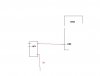
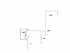
Most optos don't require the output transistor base to be connected, so you can attach the opto "transistor" as either high side or low side, so YES it's like a PNP if you want it to be.
Most optos don't require the output transistor base to be connected, so you can attach the opto "transistor" as either high side or low side, so YES it's like a PNP if you want it to be.
i have no way of measuring the pulse but i know the supply is 12v, and a additional wire color gray, says signal (this is a old coin mech i saw in the garage). there is also a selecting switch that says NO or NC, i set it to NO so the way i understand it should start from 0v not 12v.
i have no way of measuring the pulse but i know the supply is 12v, and a additional wire color gray, says signal (this is a old coin mech i saw in the garage). there is also a selecting switch that says NO or NC, i set it to NO so the way i understand it should start from 0v not 12v.
470 ohms is close enough. Check the maximum mA rating on the LED section of the opto to make sure. 470 will give you somewhere between 20-25 mA at 12V depending on the voltage drop of the LED.
If you're going to err, go on the high side. 1K will allow 10-12 mA through the LED which should be enough.
This site uses cookies to help personalise content, tailor your experience and to keep you logged in if you register.
By continuing to use this site, you are consenting to our use of cookies.

")