Electro Tech is an online community (with over 170,000 members) who enjoy talking about and building electronic circuits, projects and gadgets. To participate you need to register. Registration is free. Click here to register now.
Welcome to our site! Electro Tech is an online community (with over 170,000 members) who enjoy talking about and building electronic circuits, projects and gadgets. To participate you need to register. Registration is free. Click here to register now.
ok kpatz thank you, and when you said LED earlier im assuming you were talking about the diode inside the opto? just making sure i might be missing something lols
ok kpatz thank you, and when you said LED earlier im assuming you were talking about the diode inside the opto? just making sure i might be missing something lols
Also known as a pull-down resistor, since it holds the PIC pin to 0V when the opto's transistor is off. Without it, the opto can pull the pin high when on, but the pin will float when it's off, causing your erroneous readings.
Debouncing is different--that's dealing with the fact that switch contacts don't close/open cleanly and can cause multiple on/off cycles over a short period of time when the switch is moved/button is pressed.
theres a small hitch, the pulse coming from the coin mech happens so fast the PIC cannot read the signal. is there a way i can amplify or prolong this pulse so my PIC can read this signal? i tried to jumper wires instead of the coin mech the way you guys have taught me and the PIC received the signal pretty well. prolong pulse?
hi,
Looking at the application, why dont you use the PORTB.0 interrupt pin to detect the 'fast' pulse from the opto output, that way you dont need a 555 mono.
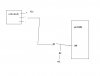
Looking at the opto isolator, unless you need isolation from the coin machine, you could just use a resistor potential divider from the 12V coin signal and connect the +5V output of the divider to pin PORTB.0.??
i wanted to isolate the 12v from 5v of my PIC so thats why the optocoupler. is this opto redundant already?
i was thinking to attach it to the trigger part of the 555, pins 4 and 5 of the Opto act like the switch instead of a push button. you think im doing this right?
about the length, enough for the PIC to detect the high so some interrupt would cause some led to light up.
hi,
Look at my previous post, thats the way I would do it, keeps the component count to a minimum [ and the cost].
Connect the 0V of the coin machine and PIC togther, power them from their own supplies of 12V and 5V. Have some decoupling caps on the PIC's +5V , say 47uF and 100nF and it should work ok.
If you are not sure about the coin machine decoupling add say 100uF and 100nF across its 12V supply.
This site uses cookies to help personalise content, tailor your experience and to keep you logged in if you register.
By continuing to use this site, you are consenting to our use of cookies.

")
")