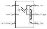
Attached is a diagram given on a data sheet for a AD6C112 optocoupler. I have been studying up on optocouplers because many of my projects need a relay, and I, more and more, am moving toward miniature projects, and modifying electric/electronic devices by adding additional features to them.
I don't quite understand the output side of this optocoupler. It is a NC devise and can switch AC and DC.
Is there anything else you think I should about this optocoupler
Thanks in advance for your help
I don't quite understand the output side of this optocoupler. It is a NC devise and can switch AC and DC.
- I believe pin 4 is the source pin (common) output requiring a connection from pin 5 or 6 to complete a circuit (ie. 12V battery & 12V relay, AC or DC).
- I believe pin 6 will pass AC or DC in my suggested circuit, so the terms "source" and "Drain" really mean just "SPST switch terminals," and will pass both phases of an AC circuit.
- The symboles before pin 5 I believe are two MOSFETs, and they only allow current to flow in one direction.
- Why are there two of them
 from the diagram, they are both connected to the same points ???
 - If one applied a AC voltage to pin 5, would the unit produce a pulsating DC (60 cycle) to the circuite

- With a DC circuit, does it matter what pin (4 or 5) is connected to the positive side of the circuit

- Why are there two of them
- Any other things I should know

Thanks in advance for your help


