Electro Tech is an online community (with over 170,000 members) who enjoy talking about and building electronic circuits, projects and gadgets. To participate you need to register. Registration is free. Click here to register now.
Welcome to our site! Electro Tech is an online community (with over 170,000 members) who enjoy talking about and building electronic circuits, projects and gadgets. To participate you need to register. Registration is free. Click here to register now.
Hi ,
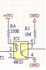
I use 4N35 to isolate a Relay . The opto's transistor's base is pulled down with a 1M resistor ,The problem is when this resistor is even touched slightly with finger the relays chatter . Here is the sch;
Hi ,
I use 4N35 to isolate a Relay . The opto's transistor's base is pulled down with a 1M resistor ,The problem is when this resistor is even touched slightly with finger the relays chatter . Here is the sch;
hi,
The 1M resistor is connected to the Base of the opto transistor, touching it will connect into the opto the background 'mains' and other electro magnetic radiation also any electrostatic field thats being picked up by your body, which acts as a receiving aerial.
sheldonstv , thanks for the ckt , but mine is a finalized PCB .
eric , yes , it chatters like a 50Hz humm 'only on touching it' otherwise not . Is it ok ? I pulled the base down to avoid any spurious triggering . But the PCB is going to be inside a closed cabinet . What to do with the base , should this be left open ckt.
hi,
I dont know what type of signals you are coupling thru the opto, but be aware adding a 100nF from the base to 0v will significantly reduce the rise and fall times of the signals.!!
EDIT: As you are using a FET to drive the relays, the heat dissipation in the FET's will be increased, also the switching point/times will be delayed.
IMHO it dosnt require a 100nF on the base of the opto, just dont touch the base.
hi dark,
If you dont feel easy with the performance of the opto, post the circuit fragment that shows the opto driver and signal, also the FET and relay part.
hi dark,
If you dont feel easy with the performance of the opto, post the circuit fragment that shows the opto driver and signal, also the FET and relay part.
This site uses cookies to help personalise content, tailor your experience and to keep you logged in if you register.
By continuing to use this site, you are consenting to our use of cookies.

")