Continue to Site

Welcome to our site!

Electro Tech is an online community (with over 170,000 members) who enjoy talking about and building electronic circuits, projects and gadgets. To participate you need to register. Registration is free. Click here to register now.

  • Welcome to our site! Electro Tech is an online community (with over 170,000 members) who enjoy talking about and building electronic circuits, projects and gadgets. To participate you need to register. Registration is free. Click here to register now.

operational amplifier circuits etc.

Status
Not open for further replies.
Thank you, MrAl.


I have never used 79xx series. Why I would need a negative supply. I believe that all I need is a 7905 and a power supply. For example, If I use a +18V power supply to power a 7905 then I can get -5V out of it, can't it?


Is this what you are suggesting? Please give it a careful look because I don't want to blow out another part.

Where should the ground of Reg #1 be connected to?

Regards
PG


Hi,

That's not exactly the circuit i was talking about because the negative lead would come from the 18v common side terminal.
Also, there may actually be a way to use the 7905 but i guess we dont really need that right now.

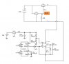
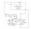
Here's a drawing for two 7805's...

Note that the resistor is required, and it must be able to pass the bias current and any circuit current that can come from the true +5v (upper 7805) line. 100 ohm is a guess and may actually have to be smaller because it has to pass the two currents with only 5v across it. With no circuit current 5/100=50ma and that should be ok, but you'll have to check your circuit current, if any. Note that current that flows from the +5v directly to the -5v is not part of Icir, only that which flows from +5 to the (new) ground is considered Icir. You'll also have to check the power dissipation as KISS pointed out.
 

Attachments

  • Dual7805Regulator-1.gif
    Dual7805Regulator-1.gif
    25.7 KB · Views: 1,484
Last edited:
Thank you, KISS, JimB, MrAl.

JimB: Sorry. It's my fault. I should have confirmed it by showing complete circuit diagram before attempting any such thing. I was fortunate that magic smoke only came out the regulator! :)

MrAl, remember this circuit we were discussing. The Vout wouldn't go above 3.6V and it wouldn't go below 0.66V. According to this table, I need it to go up to, at least, 4.67005V and go down to, at least, 0.32995V. I'm only trying to overcome this problem by making a dual supply to power the op-amp. This drawing would make it more clear. Please note that I'm using 7808 in that dual supply circuit at the top and to power up the sensor I'm using 7805.

Are you using a single 18V supply? I'm asking this because KISS was saying that I need two isolated 18V supplies.

In the drawing you can see that I left the "Ground" terminal unconnected (it's in orange highlight). Where should I connect it?

Please give it a careful look because I wouldn't be too happy to see that magic smoke again! :) Thank you.

Regards
PG
 

Attachments

  • sensor_ooo.jpg
    sensor_ooo.jpg
    85.3 KB · Views: 2,080
Last edited:
the OP said:
Are you using a single 18V supply? I'm asking this because KISS was saying that I need two isolated 18V supplies.

Well, I didn't. I said "it depends". Besides we are talking about two different kind of circuits and therefore two different answers.

A) One circuit derives + and - by a single high voltage DC source (grounded or ungrounded)
Grounded not be permissible: It depends on what the circuit connects to in the outside world.

B) Independent isolated 5V supplies. (One should be ungrounded).

Now, I still have to ask: If you take the power brick and measure the 18V out relative to the ground prong, what do you get? If it uses a 2 pin adapter, then it depends on where you are.

The (B) configuration would only matter if you were connecting this thing to say a USB port of a grounded computer. So, isolated MAY matter even with circuit (A). If (A) is an independent entity and not connected to anything, the configuration will work.

In your pic, everything to the let of Cbyp needs to be removed. Your new +5 V supply would replace it. Bypass caps should be used on the 7805's as well. do, test the +- power supply separately. There is a "slight chance" that the +5 V supply needs a minimum load.

IF and only IF the brick is grounded, you could not connect it to say a PC A/D or USB port without thinking it through. My PC brick has a 2-prong AC plug , so it's isolated.
 
Hi KISS

My charger looks **broken link removed** and these are exact specs as written on its back. It uses 2-prong AC plug.

Now could you or MrAl please help me with post #102? Thank you.

Regards
PG
 
Thank you, KISS, JimB, MrAl.

JimB: Sorry. It's my fault. I should have confirmed it by showing complete circuit diagram before attempting any such thing. I was fortunate that magic smoke only came out the regulator! :)

MrAl, remember this circuit we were discussing. The Vout wouldn't go above 3.6V and it wouldn't go below 0.66V. According to this table, I need it to go up to, at least, 4.67005V and go down to, at least, 0.32995V. I'm only trying to overcome this problem by making a dual supply to power the op-amp. This drawing would make it more clear. Please note that I'm using 7808 in that dual supply circuit at the top and to power up the sensor I'm using 7805.

Are you using a single 18V supply? I'm asking this because KISS was saying that I need two isolated 18V supplies.

In the drawing you can see that I left the "Ground" terminal unconnected (it's in orange highlight). Where should I connect it?

Please give it a careful look because I wouldn't be too happy to see that magic smoke again! :) Thank you.

Regards
PG


Hello,

Here is an update of the drawing. Note there has been a cap added to counter the bypass 0.1uf cap. The value should be something like 0.22uf, which is higher than 0.1uf.
Also note that the power supply ground is always the system ground. The 18v supply is considered to be floating.
 

Attachments

  • sensor-2.gif
    sensor-2.gif
    91.8 KB · Views: 546
Thanks a lot, MrAl.

Your drawing was very helpful.

Would it be really bad if I don't include C2 in the complete circuit? Previously, I have tested the sensor circuit using op-amp in single supple mode and didn't include any capacitors anywhere in the circuit.

Likewise is using resistor Ra really necessary? Can't I just ignore it at least during testing phase?

As I mentioned in post #104 that I will be using a laptop charger as a DC source. It outputs 18.5V.

In post #96, KISS said, "check the power dissipation (18-5) * 0.1a) IS 1.2 w". I would take he was saying that if 7805 regulator is powered by 18V and 0.1A current is being drawn then power dissipation inside the regulator is 1.2W. Do I have it correct? Thank you.

Regards
PG
 

Attachments

  • sensor_ooo_111.jpg
    sensor_ooo_111.jpg
    84.9 KB · Views: 1,012
Ra may or may not be necessary, It' more necessary if the regulators are unloaded. You effectively have to provide a boas return path to the neg of the 18V supply somehow, The 100 ohm resistor ensures that. I've see LM317's which are similar to the fixed 3-terminal regulators not work unless there was a minimum load. Bypass caps can provide leakage paths as well. The load on the negative supply (but you really don't have any) COULD provide that path. The value isn't too critical. Four 1K resistors in parallel would give you about 250 ohms. What "COULD" happen is you will get no output or no regulation.

Bypass caps definitely should be in the real design, The worst thing that could happen is that the regulators would oscillate, heat up and self-destruct. High speed circuits need them, A breadboard may provide enough parasitic capacitance to make it OK.

The resistor is more important than the cap.

==

Your understanding of the power calculation is correct.
 
Thanks a lot, MrAl.

Your drawing was very helpful.

Would it be really bad if I don't include C2 in the complete circuit? Previously, I have tested the sensor circuit using op-amp in single supple mode and didn't include any capacitors anywhere in the circuit.

Likewise is using resistor Ra really necessary? Can't I just ignore it at least during testing phase?

As I mentioned in post #104 that I will be using a laptop charger as a DC source. It outputs 18.5V.

In post #96, KISS said, "check the power dissipation (18-5) * 0.1a) IS 1.2 w". I would take he was saying that if 7805 regulator is powered by 18V and 0.1A current is being drawn then power dissipation inside the regulator is 1.2W. Do I have it correct? Thank you.

Regards
PG


Hello,

The new lower 7808 load resistor is there to counter the bias current of the upper 7808 as well as to counter any other current that is sourced by the upper 7808 that passes through the circuit (like the sensor and op amp part).
The problem is that the typical 78xx series regulators (as well as many other types) have an NPN output stage that can only source current for the most part. It can not sink current. If you pump current INTO the output (instead of the usual OUT OF) the voltage rises and that means it no longer regulates. The voltage then depends on the other circuit resistance values which can never be depended upon to regulate anything.
The new lower 7808 capacitor (0.22uf) is there to counter any capacitance of the upper 7808 and associated circuit that it powers. With 0.1uf on the output of the upper 7808 the lower 7808 must have at least an equal amount or else the transient behavior is that the lower goes unregulated just like with the resistor load problem. This problem does not exist as long as the resistor load problem because it's over after the transient dies down, but what happens in the mean time is hard to say without knowing all the internal parts in every part used in the circuit. With a larger value (0.22uf) the transient behavior is guaranteed to prevent current from flowing into the output of the lower 7808. It may still work without this cap, it depends on how the rest of the circuit behaves with an over voltage there and also if the lower 7808 can snap back into normal operation once the transient is over.

To understand this in a simplified manner, connect an imaginary ideal diode (zero voltage drop in forward mode) in series with the output of the lower 7808. Note that current can flow OUT of the regulator, but not INTO it. If current tries to flow into it, the 8v rises up to whatever the rest of the circuit dictates, and that's no longer regulation. There is also a chance that the internal transistor can blow out when this happens.

If you want to try to prove that a circuit can function without any single part, then you have to test it under every mode that it can possibly run through. In this case steady state and turn on and turn off would be three modes that it should be tested under. Evaluation would include what parts might get damaged or what parts might latch up if a given part is left out, or even if something could oscillate.
 
Status
Not open for further replies.

Latest threads

Back
Top