Hey,
I wanted to ask you guys please:
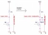
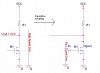
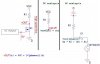
1. I read in Wiki that sometimes ICs provide a weak internal pull-up resistor to connect the drain to Vdd in order to reduce power usage by keeping input signals from floating.
How exactly does it reduce power usage?
(floating => high impedance => minumum current => minimun power usage).
2. It was also said that external strong pull-up resistor are used to minimize noise.
How does a strong pull-up reduce noise, compared with a weak one?
Thanks in advance.
I wanted to ask you guys please:
1. I read in Wiki that sometimes ICs provide a weak internal pull-up resistor to connect the drain to Vdd in order to reduce power usage by keeping input signals from floating.
How exactly does it reduce power usage?
(floating => high impedance => minumum current => minimun power usage).
2. It was also said that external strong pull-up resistor are used to minimize noise.
How does a strong pull-up reduce noise, compared with a weak one?
Thanks in advance.
Last edited:
")