Continue to Site

Welcome to our site!

Electro Tech is an online community (with over 170,000 members) who enjoy talking about and building electronic circuits, projects and gadgets. To participate you need to register. Registration is free. Click here to register now.

  • Welcome to our site! Electro Tech is an online community (with over 170,000 members) who enjoy talking about and building electronic circuits, projects and gadgets. To participate you need to register. Registration is free. Click here to register now.

Op Amp Circuit

Status
Not open for further replies.

andy001

New Member
I'm very new at this. Just started playing around with an op amp last week. I have very basic knowledge from a couple courses, but that was also a while ago.

I'm trying to amplify a small voltage (about 0-10mv from a thermocouple). I looked at some schematics & data sheets to try & design my circuit, but somewhere along the way I definitely goofed because I'm getting totally unexpected output values.

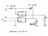
The voltage output is about 7.5v with 0v input (grounded), using a 9v source. Am I saturating the Op Amp by trying to amplify the signal too much? What is the max amplification for a typical Op Amp, and what are good resistor values to use for R1 and RF (shown in the attached diagram).

Thanks in advance!
 

Attachments

  • Op Amp TL071.JPG
    Op Amp TL071.JPG
    44.1 KB · Views: 5,771
You can't do what I think you want to do using a simple op amp as you have it. You need to first get a handle on CJC (Cold Junction Compensation) when using an op amp. You may want to give this a read.

Another problem is the output of a thermocouple is non-linear across its temperature range.

This is an example of an instrumentation amplifier designed for use with a thermocouple. Note it even provides the CJC I mentioned. There are others but that will do as an example.

What thermocouple type do you have? What is your goal with this? Then maybe we can better help you get going.

Ron
 
The TL071 is not a rail-to-rail type op amp. It can not operate with the input down to the the minus rail. You either need to go to a rail-to-rail type op amp or add a negative power supply to the op amp.
 
The circuit will work, sort of, if you do what Crutschow suggested. Since the meter - is connected to power ground, the opamp would have to be capable of rail-to-rail output, as well as having an input range all the way to the negative supply. The best way to utilize the TL0xx is to add a second 9V battery, and operate the circuit on +-9V supplies.

A thermometer built this way will not be a precision measurement tool, but you should see a meter deflection somewhat proportional to temperarure above ambient, due to the lack of a cold reference junction. The Meter movement should take less than 10mA for a full-scale deflection (or be a 0-5V voltmeter)
 
The chip Reloadron suggested is an easy way of doing it. I looked into them, but wanted to try it myself. The thermocouple is a Type k.

I may play around with CJC in future using a thermistor and a PIC, but for now I'm just trying to see if I can get the thing working. I added a negative supply as crutschow suggested (using resistors as a voltage divider) and it works (thanks!) - although my method is very rudimentary, and the op amp's internal resistance seems to be throwing things off a bit.

Mike ML (or anyone) do you have some suggestions for an op amp that is rail to rail, and allows input right down to ground? (Able to amplify the mV input without a negative source?) How non linear are thermocouples? Can you assume linearity over a small range of 10-20deg?

Out of interest, Ron - do you know if a chip like the AD595 uses a function or a lookup table to deal with non linearity?

The suggestions were all great!
 
Last edited:
Mike ML (or anyone) do you have some suggestions for an op amp that is rail to rail, and allows input right down to ground? (Able to amplify the mV input without a negative source?)

I've used the MCP619 before with pretty good success in single supply temperature and pressure sensing circuits.
 
The LM158/258/358/LM2904 have a common mode input voltage range up to 0.5V below Vss. Their output will pull within mV of Vss, but will only pull to Vdd-1.2V when sourcing current. They are very slow, but for a thermocouple sensor, they would work just fine.
 
Out of interest, Ron - do you know if a chip like the AD595 uses a function or a lookup table to deal with non linearity?

No, not that chip. However, the non linearity of a T/C is covered well in this link. See around page Z-25. Since you mention a look up table though I recall a thread awhile back in this forum where another member worked pretty in depth with a member to develop a look up table for use with a micro controller. You may want to try a few searches of the forums using key words like thermocouple and temperature. OK, type K and what specific range were you after?

CJC can be a real problem if the ambient temperature the system is used in changes (varies) quite a bit. However, if for example all the measurements are taken in a pretty controlled environment, then it can be better worked around. Not real accurate but OK for some applications.

Yeah, chips designed for this can get a little pricey. :)

Ron
 
Great link Ron! Not only does it explain the non-linearity pretty well, it also gets into the type of degradation & errors you can expect with the thermocouple over time.

Right now I'm not sure of the temperature range of the sensor. Eventually I'd like to put it into the chimney of a wood stove to monitor temperature inside. The temperature at the meter end would probably be anywhere from about -30 to 20 C (-20 to 70 F)
 
Last edited:
HI Ya

Tell you what. Give this older thread a read. If you are in the US I may be able to help you out and simplify things a little for you. They are Type J but would likely work just fine and I am sure I have a few J thermocouples lying around. You will need a 24 volt everyday small power supply and either a 250 Ohm or 500 Ohm precision resistor. I may even have a few K types with lower ranges lying around.

Ron
 
That's very generous of you! Unfortunately I'm a neighbor to the north & don't live in the States. No big deal though. I have some type K wire and a couple sealed type K thermocouples lying around in a box so it makes sense to challenge myself and learn how to do this.

The concept of CJC seems very simple. How difficult is implementation? I had planned to use a PIC with inputs from the thermocouple and from a thermistor. I looked at the Steinhart-Hart equation (used for thermistors), but as I'm not yet too familiar with PICs or programming, I don't know if it would be easily possible to program an equation using natural logarithm (ln) onto the chip? Of course I suppose a lockup table of some kind is always an option.

The curve of the thermocouple input looks like it's pretty easy to handle using the polynomial T = A0+A1X+A2X2... I'll divide the temperature range into segments and use more concise equations based on available computing power.

As for the amplification of the signal, I'm starting to get an idea of what's going on, but I've still got a long way to go. I picked up one of the op-amps (LM358) that was suggested on this forum just to try it. The specs say it has an offset voltage of 2mv which I think is a problem right? What exactly is offset voltage? Anyway, the MCP616 has an input offset of 150 µV which I think would be more compatible with amplifying mV signals.

So the big question is... Am I on the right track here with any of this? Will I ever be able to make the temperature reading accurate following this method, or should I give up on Op Amps all together and get a dedicated thermocouple IC?

Also, once again Ron, I really appreciate that offer!
 
And just a random question for vne147. Does the name make reference to the Eurocopter?
 
Last edited:
Back to Op Amps, a friend of mine is an electrical engineer and he said he had used an op amp on a project that had very low offset and low offset drift. He thought it had 3uV offset, and 60nV/deg C drift. Would this be a more appropriate amplifier for this application?
 
Low offset is important in the specs, like the MCP619 and the opamp you quoted, but you're going to find that the thermocouple effects of resistors/copper/solder can swamp the opamp. Layout is vital for good results. Keeping thermal differences of the input components to as close to zero as possible. Insulation around the input is a good idea.
 
Hi Ya Andy

The problem with all of these op amp solutions as you are beginning to see is that most don't fare well with thermocouples. Even when working with the more expensive operational amplifiers designed for thermocouple use things like parts layout on a board are critical to just get fair to good accuracy. This also involves design and layout of a board just to plant the thing on. Thermocouples can just be a ***** to work with. Strain gauge bridges for pressure and force, not too bad but thermocouples can be a nightmare, thus increased cost.

When devices like the LM335 temperature sensor can be used they are a good choice. That gives you -55 to 130 C and here is the data sheet.

If you want to go the TC route, I can send you a few of what I mentioned to Canada. I have no clue how Canada will treat a few little hockey puck temperature transmitters? I have sent things to friends in Canada and never a problem with computer parts and software too.

Ron
 
Canadian customs giving trouble for a couple items that look like hockey pucks? Of course not!!

Yeah, it seems like using thermocouples with a simple op amp (even precise ones) may be more of a headache than I first anticipated. If you still have one or two of the transmitters around I'd love to take you up on the offer and see what I can come up with! Just to clarify, are the controllers for type J or K? (The datasheet seems to indicate it can take both but I'm just making sure).
 
PM me with where to send. I have plenty of the type J I mentioned but if you PM some specific range I may be able to make that happen. No problem at all.

Ron
 
And just a random question for vne147. Does the name make reference to the Eurocopter?

No sir. VNE is an aviation abbreviation for "never exceed speed". 147 knots happened to be the never exceed speed in the dinky little Cessna 150 I flew while getting my private pilot license.
 
Gotcha! Vne in one model of the Eurocopter is also 147kts. I thought it might be an aviation reference so I figured I'd ask :) (I fly a beech for a company in Canada).
 
Status
Not open for further replies.

Latest threads

New Articles From Microcontroller Tips

Back
Top