Continue to Site

Welcome to our site!

Electro Tech is an online community (with over 170,000 members) who enjoy talking about and building electronic circuits, projects and gadgets. To participate you need to register. Registration is free. Click here to register now.

  • Welcome to our site! Electro Tech is an online community (with over 170,000 members) who enjoy talking about and building electronic circuits, projects and gadgets. To participate you need to register. Registration is free. Click here to register now.

On/Off Touch Switch

Status
Not open for further replies.

ScarEye

New Member
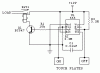
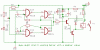
Hi, I wanted to know if anyone has made a on/off switch that is triggred by touch. I have seen some schematics out there but they contradict each other. Basically I have an electronic device which as 4 dip switches on there and they are annoying and I see some people who have just installed toggle switches instead but that looks ugly. So want I wanted to do is take the dip switches out and replace them with an "electronic on/off switch" either push button or touch activated. Does anyone here have schematics for this ? Thanks a million in advance.
 
Easy.

This information is easily available on the web!!

Do a google search for ' touch switch circuit '

and then adapt as needed.
 
This is what I had built quite long back. Works awsome!
 

Attachments

  • TouchSW.gif
    TouchSW.gif
    2.6 KB · Views: 5,829
or you want something with a single electrode?
i have built a circuit like that and it is still working fine...
if you want i can draw the schematic...
 
Wow, thanks for all the reply's guys. You guys ROCK !!! =)....

Kinja, I like that design but I prefer something with 1 electrode which I can use to turn this device on or off.

Bogdanfirst, I would appreciate that schematic with the 1 electrode.

Pilot, I am going to give that a shot also. To see what's out there.


Thanks To All

P.S. Also I would like a LED on there so I know if a design is On or Off.

I heard on some designs when the device is turned on the relay switch can land on a On of Off state and you would have to use the rest button to turn the relay switch off. Is this true ? Or does depend on the design ?

Thank You Once Again =)
 
When the circuit is 'on' current passes through the collector of the transistor. Depending on the operating voltage you select, the current passed by the transistor, and the sensitivity of the relay you pick, you probably could run your LED indicator of the same collector as you are tapping for the relay.
 
Gene, Thanks for your input. I am now just waiting on bogdanfirst to post that schematic that has been working for him for a while now.

Thank you once again =)
 
You could still use kinjals 2-electrode design, but arrange it on a PCB, so that the electrodes form concentric spirals. Thus, you only need one finger to cover both electrodes.
 

Attachments

  • spiral.jpg
    spiral.jpg
    6 KB · Views: 5,219
Phasor, Looking at kinjal's schematic (now I could be wrong) one electrode turns on it on and the other electrode turns the device off. So if I were to do what you say wouldn't I confuse it by pressing both electrodes and the same time. Because I was thinking about doing something like that but then I thought to myself that won't work.

Thanks for your reply. =)


P.S. Does anyone know if I can pick up these parts from Radio Shack I know they will have the 555 Timer IC, and the resistors but the relay switch and the transistors I don't know about. I use to have this awesome IC Cross Reference Book but it just dissapeared.


Thanks You. =)
 
I would think they would have these. Sadly, RS seems to be getting out of the parts business. I guess they didn't sell enough. They were very expensive but handy. Since you brought it up, "You've got questions, they've got answers" Right? Well, just for fun, ask the clerk what he recommends for biasing, buffering, or decoupling your IC. Na, don't really do it. Not sure where that mean streak came from - sorry.
 
Radio Shack
"You've Got Questions, Ahhh So Do We"

Or

Radio Shack
"You've Got Question, How The F**k should we know"


I don't want to get off the topic but since Gene started this. Id thought I would continue. =)
 
well i said i have a touch swtich, so here is the schematic.
i'll explain a bit. the circuit works fine with 5-15V, it all depends on what voltage you use for the relay.
the second thing is the led, why i put it here. the way i made the touch switch is:
i took the led and put some turns of uninsulated wire around it and connected it to the sensor. then i covered the led's leads with a plastic tube. it looks very nice and if you touch the led the circuit turns on or off the lamp.
another thing is the 10M resistor. you might find that the circuit will be working better with a smaller value like 4M7 or 3M5. it depends on wht type of ic you use. i used one from philips, it works fine, and i have the circuit for quite some time functioning full time.
 
well i have the schematic. if you need more explications tell me.
the circuit operates from 5 to 15V
 

Attachments

  • touch.gif
    touch.gif
    6.9 KB · Views: 5,456
bogdanfirst, I like that idea with the wires around the led. Did you have to cover the whole led with wire. In other words in order for the device to switch on or off your fingers would have to make direct contact with the sensor correct ? And where did you get your parts from ? Can I pick them up at RatShack or do I need to go through digikey or jameco or something.

Thanks for the reply =)
 
well, i did not cover all the led...i used a 5mm led and covered it abut 2/3 of it leaving the end of it free. the thing is that when you put your hand on the led you got to touch the wire too.
another thing...i put a wrong value to R6(origlnally 1K8) if you put the led put a smaller value like 1K or 800R.
about the parts, i dont know, here there are not all the shops that you say.
the ic, the 4011, i used a HEF401BP, from philips. it works fine, i have a small light like that by the bed and i always turn it on at night when i am not carefull(i moove a lot when i sleep) and wake up to turn it off :lol:
about the other components, i used 2 bc171 thats what i had then. for the bc171 you can use a general purpose thansistor, low power, but in place of the bc 140, you can put a transistor that can handle the current of the led. bc140 can hold 1A wich i thing is enough.
 
Here are a couple:

**broken link removed**

personally, I like the ones already discussed.
 
What does the "R" stand for in a resistor. For example 330R. Does that mean Ohms. And also 1k8 <---- What's the 8 for?. You think you know almost everything just to find out you know nothing. lol

bogdanfirst, what type of relay switch is that SPST ? And what type did you use (part #)

Gene, I like the one we already discussed also but that double electrode is going to make my project look messy. But it looks real easy to make.


Thanks =)
 
330R means 330 Ohms
1k8 means 1.8k . The character in the middle acts as decimal point in all cases like 2M7 means 2.7M.
SPST relay is SINGLE POLE SINGLE THROW type of relay having only one on/off contact.
 
Phasor, Looking at kinjal's schematic (now I could be wrong) one electrode turns on it on and the other electrode turns the device off.

Sorry, I didn't pay enough attention :oops:
 
Status
Not open for further replies.

Latest threads

New Articles From Microcontroller Tips

Back
Top