Continue to Site

Welcome to our site!

Electro Tech is an online community (with over 170,000 members) who enjoy talking about and building electronic circuits, projects and gadgets. To participate you need to register. Registration is free. Click here to register now.

  • Welcome to our site! Electro Tech is an online community (with over 170,000 members) who enjoy talking about and building electronic circuits, projects and gadgets. To participate you need to register. Registration is free. Click here to register now.

number of poles, back EMF, etc, in an induction motor

Status
Not open for further replies.

PG1995

Active Member
Hi,

In an induction motor, i.e. asynchronous AC motor, as number of poles is increases synchronous speed decreases where synchronous speed is speed of rotating magnetic field. The relationship is given as Ns = 120*f/P.

1: Is it true that the minimum number of poles for a single AC phase motor is two, and minimum number of poles for a three phase motor is six?

2: I understand that the number of poles should always be even, i.e. 2, 4, 6. Why is it important to have same number of poles per phase? For example, for a three phase inductor motor, for phases A and B the number of poles is doubled, i.e. 8, but the number of poles for phase C are kept constant, i.e. 2. It would give the total of poles 10. Would having 10 poles instead of 12 make motor motion jerky?

3: What's the point of having more number of poles than the minimum, or how does it help increasing the number of poles? I'd say that having more poles provide motor more torque.

Thank you!
 
The minimum for a single phase is two and for three phase is three.
That gives one rotation per complete AC cycle.

For a motor to run on a conventional three phase AC supply, you must remember that the phases are in a fixed relationship, 120 degrees apart.

For a rotational machine with three poles, you can imagine that as three equally spaced points rotating around the circumference of a circle.
With six poles, six points with the same phase duplicated 180 degrees out for all three.

The rotor will have the same number of poles.

The only way they can all "pull" together and equally is if everything matches up as a multiple of three - try drawing it out yourself, a rotating circle inside a fixed circle - you will get uneven forces or no rotation with any other combination of numbers.


One of the big advantages of three phase over single phase is that the motor torque is absolutely constant as it rotates, there is no unevenness or vibration. That only works when the physical pole arrangements are perfectly positioned.


There are other combinations used with motors intended for different power sources - eg. "Brushless DC" servo motors as used in machine tools use a three phase style stator with with a two pole permanent magnet rotor.

There is a position sensor on the rotor and the drive electronics use that and the required torque to apply power to the appropriate combination of stator windings to pull the rotor around.
 
Hi,
In an induction motor, i.e. asynchronous AC motor, as number of poles is increases synchronous speed decreases where synchronous speed is speed of rotating magnetic field. The relationship is given as Ns = 120*f/P.

Except an Induction motor can never be synchronous. There will always be a slip frequency present.
Max
 
Thank you!

The minimum for a single phase is two and for three phase is three.

I'm sorry but are there really three number of poles in case of three phase? You can say either say that there are three pole pairs or there are in total six poles as is shown below.

1576307720385.png


Thanks for your help!
 
The formulae to calculate the RPM of an AC induction motor is the same for 1ph, i.e. a 2 pole 3phase motor has six windings.
The RPM is exactly the same as a 2 pole 1ph.
Max.
 
The more pairs the faster the motor speed.
Sorry shortbus, you have that the wrong way around.
The more pole pairs, the lower the speed.

JimB
 
You can say either say that there are three pole pairs or there are in total six poles as is shown below.

I'm reasonably well up on the physical arrangements but it seems I'm using the wrong terminology - thinking poles as physical pole winding angles instead of coil "sets", as in the number involved in one AC cycle sequence.


As you say, each physical pole uses a pair of coils to induce a field through the rotor.

Three angular sets / three pairs / six individual pole pieces gives one full rotation of the field, eg. with each of the six becoming a "north" in sequence, per AC cycle.

The more pole sets there are, the slower the motor rotates for a given frequency.
 
Thank you!

Question 1:
Ns / rotating magnetic field speed / synchronous speed = 120*f/(number of poles per phase)

For a three phase induction motor, if number of poles are increased from 6 to 12, it would take 2 electrical cycles for each complete one mechanical cycle. It brings me back to my original Question 3 from post #1: What's the point of having more number of poles than the minimum, or how does it help increasing the number of poles? I'd say that having more poles provide motor more torque. You are spending more 'electrical' energy per mechanical cycle so it would give you more torque (J/radian) at the expense of less speed. Do I make sense?

Question 2:
You can see in the plot below that at "100" along the horizontal axis, the torque/current are "0". It doesn't make sense to me and it looks like I'm not reading the plot correctly. At "100" the motor is free running without any load and the rotor speed and stator speed are ideally the same. The torque and current can not be "0".

Question 3:
I'm reading the plot from right to left. At "100" along the horizontal axis, the motor is freely spinning, then it is gradually loaded, the torque starts increasing and so does the current and slip. The torque keeps on increasing until "break down torque" point is reached. Beyond this point moving toward left along the x-axis, the torque would keep on decreasing for increasing load.

When the motor is spinning freely, the rotor and stator rotate at the same speed or frequency. The back emf or counter-electromotive force generated in stator windings by the rotor controls the current flowing in stator windings. As the load starts increasing, the slip also starts increasing which means rotor's speed starts decreasing in reference to stator's speed. It would mean that the stator's magnetic field cuts the stator windings at reduced rate and this would result into reduced back emf in stator's windings. This reduced back emf would let more current into stator's windings which would result into stronger magnetic poles. These stronger magnetic poles would pull the rotor more strongly. If the load keeps on increasing, this process would go on until "break down torque" point is reached. Why does the torque start decreasing beyond "break down torque" point?

induction_motor_slip-jpg.122073

Source: https://www.engineeringtoolbox.com/electrical-motor-slip-d_652.html

Helpful links:
1: https://www.engineeringtoolbox.com/electrical-motor-slip-d_652.html
2: https://www.engineeringtoolbox.com/synchronous-motor-frequency-speed-d_649.html
3: https://en.wikipedia.org/wiki/National_Electrical_Manufacturers_Association
4: https://en.wikipedia.org/wiki/International_Electrotechnical_Commission
5: https://drive.google.com/file/d/1T-yg29tnH1-4vLmTni99kX-ZI38zeJrd/view?usp=sharing
 

Attachments

  • induction_motor_poles_1.jpg
    induction_motor_poles_1.jpg
    287.1 KB · Views: 339
  • induction_motor_slip.jpg
    induction_motor_slip.jpg
    54.3 KB · Views: 787
Last edited:
What's the point of having more number of poles than the minimum, or how does it help increasing the number of poles? I'd say that having more poles provide motor more torque. You are spending more 'electrical' energy per mechanical cycle so it would give you more torque (J/radian) at the expense of less speed.
Also consider the wider mechanical aspects of the motor.
A single pole-pair motor will run at just under 3000 RPM on a 50Hz supply.
That would be OK for a small fractional horse power that you could pick up with one hand, but consider a large motor, say 1000HP, you may not want it whizzing around at 3000 RPM when the thing that it is driving needs to run at a slower speed.

JimB
 
Thank you, JimB.

I hope someone could also help me with Question 2 and Question 3 from the previous post.

I also have a general question about the types of motors. I'm sure there are many different types of motors and those could be categorized in so many different ways as well.

Please have a look on the attachment. motor_tree
Sources:
1: **broken link removed**
2:

To me, the tree on left looks more descriptive and well categorized. Do you also think so?

Also, there is something confusing in the table on right. In the table on left, you could see that "Split Phase" has four sub-categories under it, which are "Capacitor start", "Capacitor run (permanent-split capacitor)", "capacitor start/run", "Resistance start". The table on right has these mixed up, in my opinion. Do you agree?

Thank you!


Helpful links:
1: http://www.interfacebus.com/Stepper_Motor_Manufacturers.html
2: http://electrical-engineering-world1.blogspot.com/2015/01/types-of-motors.html
3: http://imageshack.com/a/img923/7751/14Eocj.png
 

Attachments

  • motor_tree.JPG
    motor_tree.JPG
    211.7 KB · Views: 351
For question 2.

If there is no difference at all between the speed the field is rotating it in the stator and the speed the rotor is turning at - they are in effect stationary relative to each other and no current is induced in the rotor - so no torque.

It needs some "slip" and relative movement to induce current in the rotor and provide some torque.

It will never actually run at synchronous speed, even with zero load.


Up to a point, more slip means higher current and higher torque - but if there is too much slip, eg. the rotor position has changed too much relative to the rotating field in the stator, the current transfer efficiency drops off and torque reduces again.

Think of it a bit like stepper motor - load it too much and the rotor slips rather than following the stator coil field. With an induction motor the rotor poles are induces rather than permanent, but the effect is not all that different, there is a limit to the torque or rotational "pull" a given size and construction rotor can achieve.


Re. the motor "trees," they are just different people interpretations. There are lots of crossovers in technology between different motor classes.
eg. A three phase motor will work like a capacitor run one on single phase, and a similar stator could be used in a brushless DC motor design.


Having more pole sets in effect gives electrical "gearing" to produce a lower speed, higher torque output without the need for a mechanical gearbox.
Induction motors can have two or more sets of windings for multiple speeds - I rebuilt the controls on a machine with a four speed induction motor last year. That had two electrically separate sets of two-speed (seven terminal) windings, giving two pole, four pole, six pole and twelve pole configurations.

eg. Two sets of winding like this (each with a break at one point, so seven terminal each) with the coils spread over different numbers of stator slots so different sets of angles between them and different speed combinations...
 
Question 2:
You can see in the plot below that at "100" along the horizontal axis, the torque/current are "0". It doesn't make sense to me and it looks like I'm not reading the plot correctly. At "100" the motor is free running without any load and the rotor speed and stator speed are ideally the same. The torque and current can not be "0".
Having looked at the graph which you have posted, and the source where it came from, I am of the opinion that it is simplistic and wrong. Very wrong.
An induction motor NEVER runs at its synchronous speed, there is always some slip between the rotating magnetic field in the stator and the rotor mechanical speed.
If there is no slip, there is no current induced in the rotor conductors, hence no torque to turn the rotor.

I am not an expert on induction motors and further analysis of their operation does not interst me at the moment. Sorry.

Please have a look on the attachment. motor_tree
Sources:
1: **broken link removed**
2:

To me, the tree on left looks more descriptive and well categorized. Do you also think so?

Also, there is something confusing in the table on right. In the table on left, you could see that "Split Phase" has four sub-categories under it, which are "Capacitor start", "Capacitor run (permanent-split capacitor)", "capacitor start/run", "Resistance start". The table on right has these mixed up, in my opinion. Do you agree?
This just seems to be "analysis and categorisation to absurdity"
At a quick overview, they seem to be two different peoples views of a complicated subject.

JimB
 
If you look at an industrial 2 pole motor 1 or 3 phase the rating plate usually says 2880 rpm no load (50hz), even though the field within rotates at 3000 rpm, the reduction is due to the slip, the more load to an extent the more slip.
I've always thought of an induction motor as semi synchronous, as to control the speed of an induction motor you control the frequency, this is done on about every machine I've worked on.
Single phase motors usually require an artificially made second phase, ie from a capacitor, a shunt winding, a copper magnetic shunt, shaded pole etc.
What exactly do you need to know, or is this just for discussion.
 
Thanks a lot, everyone!

For question 2.

If there is no difference at all between the speed the field is rotating it in the stator and the speed the rotor is turning at - they are in effect stationary relative to each other and no current is induced in the rotor - so no torque.

It needs some "slip" and relative movement to induce current in the rotor and provide some torque.

It will never actually run at synchronous speed, even with zero load.

Yes, practically it cannot but in Question 2 of post #11, I was only considering an ideal scenario; from post #11: "the rotor speed and stator speed are ideally the same". In a practical scenario, even when a load is absent there are always going to be friction, windage, inefficiency in rotor magnetization. In an ideal scenario when no load is present, other factors could be ignored and the rotor and stator speeds could be the same, in my humble opinion.

Up to a point, more slip means higher current and higher torque - but if there is too much slip, eg. the rotor position has changed too much relative to the rotating field in the stator, the current transfer efficiency drops off and torque reduces again.

This is a very good point. To me the situation is more confusing than what was stated earlier by me. Anyway, the first question would be that why the current transfer efficiency drops.

Looking at the plot from post #11, there is another related interesting point. Beyond the "break down torque" point moving toward left from right, the current doesn't exceed that much considering that the slip increases. Although the increasing slip would mean rotor cuts the stator less and less which in turn should result into less and less back emf in stator windings which means the current in stator should rise significantly. But the current in stator windings doesn't exceed significantly with increasing slip beyond the "break down torque" point and this is one of the reasons that torque starts decreasing instead of increasing.

Having looked at the graph which you have posted, and the source where it came from, I am of the opinion that it is simplistic and wrong. Very wrong.
An induction motor NEVER runs at its synchronous speed, there is always some slip between the rotating magnetic field in the stator and the rotor mechanical speed.
If there is no slip, there is no current induced in the rotor conductors, hence no torque to turn the rotor.

I'm sorry but I beg to differ on this one. I don't think the plot is wrong. It's considering an ideal scenario ignoring friction, windage, inefficiency involved in rotor magnetization. If you Google terms like "induction motor speed torque slip current", you would many similar looking plots.

What exactly do you need to know, or is this just for discussion.

Just for discussion and to understand it in detail.

Thank you for the help.
 
Yes, practically it cannot but in Question 2 of post #11, I was only considering an ideal scenario; from post #11: "the rotor speed and stator speed are ideally the same". In a practical scenario, even when a load is absent there are always going to be friction, windage, inefficiency in rotor magnetization. In an ideal scenario when no load is present, other factors could be ignored and the rotor and stator speeds could be the same, in my humble opinion.

As several posts have said, it has Nothing to do with friction-windage-inefficiency, as its name implies, a AC induction motor requires induction from stator to rotor which cannot exist when they are both in syncronism.
There used to be a popular motor the detected when the rotor was a few cycles away from sync, and at that point DC would be injected into a set of rotor windings, pulling the motor rotor into synchronism.
Max.
 
In an ideal scenario when no load is present, other factors could be ignored and the rotor and stator speeds could be the same, in my humble opinion.

No - absolutely not.

As Max has also confirmed: No relative motion between the rotation of the stator field and rotor means ZERO energy transfer.

The only way in the real world you ever see the very right side of that plot is if the rotor was externally driven by a separate variable speed motor. The current would then drop to a minimum at synchronous speed and start to increase again beyond that.


Re. slip and lower speeds:
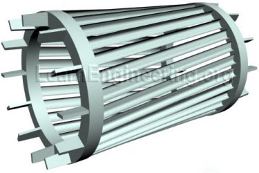
The rotor is a squirrel cage consisting of "shorted turns" - linked copper bars.

squirrel_cage_rotor.jpg


The currents induced in those can be massive and the resulting magnetic field also extremely strong.

The shorted turn "coils" are inductors.

If the rotor rotates at near the speed of the stator field, the induced magnetic poles stay near in line with the stator poles.

When the slip becomes too great, the poles are too far out of line to maintain the maximum induced field.
The poles and circulating current then have to re-align at every half cycle so the inductance of the rotor means the maximum field is never achieved.

Remember that an AC electromagnet is used to demagnetise or degauss objects.

With too great an angular change, the rotor field has to be rebuilt every half cycle rather than being boosted at only a fractionally different angle every half cycle.

That's why the starting torque is low and the starting current high.


Out of curiosity, the angular changes...

Synchronous speed 1500 RPM, Nominal speed 1440:
That's 60 rpm difference, 1 rev per second.

With three phase 50 Hz, there are six AC peaks (and so pole shifts) per cycle; 300 per second.

That puts the peak torque rotational slip or "drift" between the rotor and stator at around 1.2 degrees per half cycle.
 
As several posts have said, it has Nothing to do with friction-windage-inefficiency, as its name implies, a AC induction motor requires induction from stator to rotor which cannot exist when they are both in syncronism.

I'm sorry but my intent was not to negate anyone. I have read at some places that under no frictional losses and no-load, the stator and rotor rotate at synchronous speed. Please check the first answer: https://www.quora.com/An-induction-motor-cannot-run-at-synchronous-speed-Why . It's only one of such articles I have come across. I believe I have heard the same thing in a video(s) as well.

Thank you!
 
Status
Not open for further replies.

Latest threads

New Articles From Microcontroller Tips

Back
Top