Continue to Site

Welcome to our site!

Electro Tech is an online community (with over 170,000 members) who enjoy talking about and building electronic circuits, projects and gadgets. To participate you need to register. Registration is free. Click here to register now.

  • Welcome to our site! Electro Tech is an online community (with over 170,000 members) who enjoy talking about and building electronic circuits, projects and gadgets. To participate you need to register. Registration is free. Click here to register now.

number of poles, back EMF, etc, in an induction motor

Status
Not open for further replies.
I have read at some places that under no frictional losses and no-load, the stator and rotor rotate at synchronous speed.

The only way that could happen is if there were a residual permanent magnetic field in the rotor.
It's not by design in a normal induction motor and probably means it's a lower quality motor with a poor grade of iron laminations, or the motor shaft itself is magnetised.
 
Seeing as this is for discussion.
You can use an induction motor as a generator, I tried, you need to give the system a 'kick', I used a dc pulse from a small battery.
Point is the same works in reverse, to get the rated power you need to turn the rotor faster, ie if the motor is 2880 rpm (which is 3000 synchronous speed - 20) then you need to turn the motor at 3020 rpm, the energy required to turn the rotor the extra 20 rpm is mostly used up magnetizing the rotor.

There is one synchronous propery about an induction motor, the field within the core does rotate synchronously, I guess a noob could mistake that for the rotor and therefore o/p shaft.
 
The rotor is a squirrel cage consisting of "shorted turns" - linked copper bars.

The currents induced in those can be massive and the resulting magnetic field also extremely strong.
The shorted turn "coils" are inductors.

On a related note, early in my career training, I did a stint in the motor winding dept, at that time the copper bars were silver soldered at the shorting plate ends, motors would come in where the rotor had got so hot they had flung the solder, the result was the motor did not rotate and the current was practically zero.
Now they are usually cast and machined into the rotor.
Max.
 
See P34 for making/modifying close to synchronism motor by removing induction motor rotor bar segments.
Ach, the site does not allow large files!:(
Here is one page .
OK, here is the original link, first item in the list.
Max.
 

Attachments

  • reluctance M.jpg
    reluctance M.jpg
    39.9 KB · Views: 116
Last edited:
Hi Max,
I served my apprenticeship in the winding dept.
I saw only a couple of soldered bar rotors, the majority were cast ally endcaps, that must have been a while back.
 
Very old motors from from 1950s and older were usually designed to have 3 windings for 1 voltage like 220v or 440v or other. Voltage was standardized about 50 years ago to, 120, 240, 480.

Most modern day motors have 6 windings that can be connected 2 different ways for 240v and 480v

There are other 3ph motors designed for other voltages maybe as many as 4 different voltages.

There are also high voltage 3 ph motors made to be small with lots of power that run on 5000 volts. A 100hp motor looks small with a very large diameter shaft that looks strange compared to other motors.

I looked online for 45 minutes there are no drawings anymore to show internal wiring of a 3 ph generator vs a 3 ph motor so you can understand why they are designed and wired the way they are. 3ph motor windings match 3ph generator windings. A single ph motor uses only 2 of a 3ph wires.

3 ph motor will always have 3 windings but that winding can me made up of several windings in series or parallel so motor voltage matches line voltage.

Single phase motor with 2 winds are high RPM motors about 3400 RPM and 4 windings are lower RPM about 1700 RPM.

Internal motor windings can be wired different so motor will run at other RPMs like, 900, 1100, 1200, 1400, 1600, 1700, 1800. Look online at WW Granger at all the motors they sell.

Here is a photo of the tag on a 3 ph motor it can be wired 240v with windings connected in parallel or 480v with windings connected in series.

Here is a drawing I made that shows motors vs a 3ph generator.


KmuB3.jpg


100_5843.JPG
 
Last edited:
Before my time, that would have been back when the likes of brush & brook crompton were in their hay day.
 
If the rotor rotates at near the speed of the stator field, the induced magnetic poles stay near in line with the stator poles.

When the slip becomes too great, the poles are too far out of line to maintain the maximum induced field.
The poles and circulating current then have to re-align at every half cycle so the inductance of the rotor means the maximum field is never achieved.

Remember that an AC electromagnet is used to demagnetise or degauss objects.

With too great an angular change, the rotor field has to be rebuilt every half cycle rather than being boosted at only a fractionally different angle every half cycle.

That's why the starting torque is low and the starting current high.


Out of curiosity, the angular changes...

Synchronous speed 1500 RPM, Nominal speed 1440:
That's 60 rpm difference, 1 rev per second.

With three phase 50 Hz, there are six AC peaks (and so pole shifts) per cycle; 300 per second.

That puts the peak torque rotational slip or "drift" between the rotor and stator at around 1.2 degrees per half cycle.

Thanks a lot. It was really helpful and I was able to picture it better. I have repeated your words below using a single phase motor.

Suppose a single phase capacitor start induction motor

Suppose synchronous speed or rotating magnetic field speed is 3600 RPM, nominal speed or rotor speed 3540 RPM:
that's 60 RPM difference, 1 rev per second. In other words, rotor falls back 1 rev or 360 degrees per second in relation to the rotating magnetic field speed.

With a single phase 60 Hz, there are two AC peaks (and so pole shifts) per cycle; 120 peaks per second. Or, we can say that there are 120 half cycles per second.

{360 degrees per second} / {120 half cycles per second} = 3 degrees per half cycle

That puts the rotational slip or drift between the rotor and stator at around 3 degrees per half cycle.

Just to confirm:
3540/3600 = 0.98333333
0.98333333*360=354
full cycle: 360-354=6
half cycle: 6/2 = 3 degrees
120*3=360 degrees


The only way that could happen is if there were a residual permanent magnetic field in the rotor.
It's not by design in a normal induction motor and probably means it's a lower quality motor with a poor grade of iron laminations, or the motor shaft itself is magnetised.

So, under no frictional losses and no-load, the stator and rotor rotate will still have some minimum slip; in other words, the rotor would lag behind the rotating magnetic field by some least degree. I do understand that induction motors come in different sizes and different designs but is there a way to know how much slip would there exist between the stator and rotor under no frictional losses and no-load? Is it almost negligible?


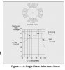
The following picture shows stator windings for a single phase induction motor. We can say that during one half cycle, the upper winding would act like a north pole and in later half cycle, it become a south pole, and so on. It makes sense.

induction_motor_stator_1.png


I was watching this video and how the winding is shown doesn't look correct to me. Please watch it from 1:22 to 1:41. It only shows a single loop and it looks wrong how North and South poles are shown. Do you agree? Thank you.

 
Thinking about magnetic fields makes my head hurt!

But looking at 2:02 in the video and applying the right hand screw rule, I think that the N and S are in the right place.
What is confusing is that the N and S are adjacent to the current indicator arrows on the other wire.

JimB
 
and applying the right hand screw rule, I think that the N and S are in the right place.

Thank you but I don't get it. The right hand screw rule gives the direction of circular magnetic field and in such a case north and south poles don't really matter. In Figure 2 below, each pole acts like a solenoid. For example, when B1 is north pole, B2 becomes south pole, and B1 and B2 represents a single phase and the wire in wound such a manner that when B1 is north pole, the direction of current in B2 produces south pole. The same goes for the other phases.

Figure 1:
1577251967633.png


Figure 2:
1577252533155.png
 
{360 degrees per second} / {120 half cycles per second} = 3 degrees per half cycle

That puts the rotational slip or drift between the rotor and stator at around 3 degrees per half cycle.

Just to confirm:
3540/3600 = 0.98333333
0.98333333*360=354
full cycle: 360-354=6
half cycle: 6/2 = 3 degrees
120*3=360 degrees

Yep, that looks about right - but for any single phase squirrel cage induction motor there will be a starting or start/run winding 90' out, adding phase shifted half cycles, so you could consider it 1.5 degrees per pole slip.
 
but for any single phase squirrel cage induction motor there will be a starting or start/run winding 90' out, adding phase shifted half cycles, so you could consider it 1.5 degrees per pole slip.

I did think about it but if it's just a capacitor start motor, the start winding could be excluded and there would only be two poles, and 3 degrees per half cycle would be correct. Don't you think so?

Which one provides more starting torque, capacitor-start motor or capacitor-start-and-capacitor-run motor? The start capacitor is always quite bigger compared to the run capacitor. Two capacitors in parallel give more capacitors or a resultant bigger capacitor, so in my view capacitor-start-and-capacitor-run motor should provide more starting torque. Do you agree? Thanks a lot.

1577348425251.png


PS: I found the answer and it looks like I was correct.

1577349545476.png

Source: https://isccompanies.com/parts-distribution/motors/ac-motors/


Note to self:
watch videos "induction_motor_rotor_speed_slip" and "induction_motor_slip_torque_curve"

The following links are helpful for information on capacitor start, capacitor start/capacitor run, capacitor start/run without centrifugal switch.
1: https://electronics.stackexchange.c...itor-start-and-capacitor-run-induction-motors
2: https://www.quora.com/What-is-the-d...tor-start-and-a-capacitor-run-induction-motor
3: https://www.quora.com/What-is-a-capacitor-start-capacitor-run-in-a-motor
4: https://www.freedomhvacal.com/technical-hvac/blog-start-run-capacitor/
5: /watch?v=N7TZ4gm3aUg (very good video about induction motor)
6: /watch?v=pbg_PF6MTwY (very good video about starting a single phase induction motor)
Why does induction motor draw heavy current at starting?
7: https://www.quora.com/Why-does-induction-motor-draw-heavy-current-at-starting
8: https://www.quora.com/Why-is-the-st...igh-Does-it-have-any-relation-with-a-back-EMF
Star delta starter for induction motor:
9: /watch?v=h89TTwlNnpY
 

Attachments

  • 1577349507782.png
    1577349507782.png
    10.3 KB · Views: 110
Last edited:
Which one provides more starting torque, capacitor-start motor or capacitor-start-and-capacitor-run motor? The start capacitor is always quite bigger compared to the run capacitor. Two capacitors in parallel give more capacitors or a resultant bigger capacitor, so in my view capacitor-start-and-capacitor-run motor should provide more starting torque. Do you agree? Thanks a lot.

No. The run capacitor adds nothing to the start of the motor. That's why it's called a "run capacitor".
 
The run cap effect on starting I would describe it as more like an 'insignificant influence' on the starting due to its low value compared to the high value required for the start capacitor.
M.
 
Thank you!

The run capacitor adds nothing to the start of the motor.

In my humble opinion, I wouldn't say that it adds nothing to the starting torque.

The run cap effect on starting I would describe it as more like an 'insignificant influence' on the starting due to its low value compared to the high value required for the start capacitor.

Agreed. The effect would be insignificant because start capacitor is at least ten times bigger than the run capacitor. Source: https://www.freedomhvacal.com/technical-hvac/blog-start-run-capacitor/
 
In my humble opinion, I wouldn't say that it adds nothing to the starting torque.

Like Max said it adds so little it is insignificant. It is just like a capacitor start only motors rotating field. The run cap is just helping the run field do it's job better.
 
The induction motor never runs at synchronous speed. The speed of the rotor is always less than that of the synchronous speed. If the speed of the rotor is equal to the synchronous speed, no relative motion occurs between the stationary rotor conductors and the main field.

Reference - Slip in Induction Motor
 
Last edited:
Status
Not open for further replies.

Latest threads

New Articles From Microcontroller Tips

Back
Top