PG1995
Active Member
Hi,
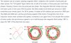
In an induction motor, i.e. asynchronous AC motor, as number of poles is increases synchronous speed decreases where synchronous speed is speed of rotating magnetic field. The relationship is given as Ns = 120*f/P.
1: Is it true that the minimum number of poles for a single AC phase motor is two, and minimum number of poles for a three phase motor is six?
2: I understand that the number of poles should always be even, i.e. 2, 4, 6. Why is it important to have same number of poles per phase? For example, for a three phase inductor motor, for phases A and B the number of poles is doubled, i.e. 8, but the number of poles for phase C are kept constant, i.e. 2. It would give the total of poles 10. Would having 10 poles instead of 12 make motor motion jerky?
3: What's the point of having more number of poles than the minimum, or how does it help increasing the number of poles? I'd say that having more poles provide motor more torque.
Thank you!