Continue to Site

Welcome to our site!

Electro Tech is an online community (with over 170,000 members) who enjoy talking about and building electronic circuits, projects and gadgets. To participate you need to register. Registration is free. Click here to register now.

  • Welcome to our site! Electro Tech is an online community (with over 170,000 members) who enjoy talking about and building electronic circuits, projects and gadgets. To participate you need to register. Registration is free. Click here to register now.

Not 200nS per cycle with 20MHZ XTAL?

Status
Not open for further replies.

Roger_NO

Member
Hi,

I'm trying to get a pulse to be 200ns. From what i have read, this can be accomplished by using a 20MHz crystal. I use a 12F683 and the capacitance with the crystal is 22pF.

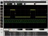
When i scope the output the pulse width is 600nS. Why is it not 200? Also when scoping the crystal it shows 6.6MHz and not 20MHz.

I have attached both my code and the screen dump from the scope.

Thanx.
 

Attachments

  • Code.txt
    512 bytes · Views: 184
  • 12F683.jpg
    12F683.jpg
    144.8 KB · Views: 319
Last edited:
200nS to 600nS is off by exactly the same ratio as the 20Mhz to 6.6Mhz error of 3:1.

Your code is probably OK, but you have an error with the crystal oscillator. Double check your hardware and config settings.
 
I recently had the same problem myself.
I wanted to clock a PIC at 20Mhz, but the 20Mhz crystal was running at 6.67Mhz.

The thing is, crystals are often operated in "overtone" modes. It is common for the crystal to operate at 3, 5 or 7 times their fundamental frequency.
In your case, the crystal is operating on its fundamental frequency rather than its third overtone.
Usually the way to make the circuit work on the third overtone is to reduce the gain at the fundamental frequency, often by including a tuned circuit tuned to the third overtone frequency.

How did I overcome the problem?
I chickened out and used a 20Mhz oscillator module rather than a crystal. ( I had the 20Mhz oscillator on hand, so it was the easy way out).

JimB
 
How did I overcome the problem?
I chickened out and used a 20Mhz oscillator module rather than a crystal. ( I had the 20Mhz oscillator on hand, so it was the easy way out).

JimB

ok, thanx. I'll try that instead. I have tried with many 20mhz crystals but they all acted the same. Funny thing is that once i turned the circuit on, it oscillated at 20mhz for a little while, then it dropped.
 
Why isn't this a problem with 4MHz quartz?
Low frequency crystals operate in Fundamental Mode.
Higher frequency crystals are usually overtone types.


Funny thing is that once i turned the circuit on, it oscillated at 20mhz for a little while, then it dropped.
You may want to try adding a high value resistor in series with the crystal, as per the Microchip data sheet for the PIC.
Reducing the gain of the oscillator loop may persuade the crystal to operate on the third overtone.

JimB
 
Low frequency crystals operate in Fundamental Mode.
Higher frequency crystals are usually overtone types.


You may want to try adding a high value resistor in series with the crystal, as per the Microchip data sheet for the PIC.
Reducing the gain of the oscillator loop may persuade the crystal to operate on the third overtone.

JimB

I tried to add a resistor from 1 up to 10 meg. the cycle time went from 600ns to 1us on all atemts.(1us). I'll just order an 20mhz oscillator:p
 
Oscillators specifically made to operate on crystal overtones are different than ones made to operate on the crystal fundamental frequency. They include LC elements that kill the gain of the oscillator at the fundamental frequency but boost it at the 3rd, 5th or 7th overtone. The internal oscillator in the PIC is capable of fundamental operation only.

The cutoff frequency where crystals are manufactered to be either a fundamental or an overtone crystal is about 20Mhz. That means if you grab an odd 20Mhz crstal out of the junk box, the manufacture could have specified that that particular crysal is to be used in a fundament mode, or that it was intended to be used in overtone mode. The data sheet (if you had it) would specify this. Without the data, you are guessing.

Note that a fundamental crystal will likely oscillate at it's overtones if placed in the correct oscillator, but its overtones are not exactly three, five or seven times the frequency stamped on the crystal. Similarly, if a crystal is intended to be used on a specific overtone, then it will not fundamentally oscillate exactly at one/third, one/fifth, one/seventh, etc., but it will be close to that.

btw- the period of a 20MHz oscillator will never be 200ns, it will be 50ns.
 
Last edited:
I found a 20MHz oscillator, so i'll use that! Thanks for the help, I'll use this information the next time I'm gonna use a high frequency crystal, but right now I don't have time to test and make the extra circuitry:p


Roger
 
20 MHz is not likely an overtone crystal. What situation you may have is your circuit does not have enough loop gain to operate at 20 MHz with the feedback setup you have with parasitics of layout/hookup but enough gain to operate as a lower frequency RC oscillator.

A fundamental mode 20 MHz crystal will look like a capacitor below its mechanical resonance. In range of 6 pF.

One sure sign it is not operating at the piezo resonance frequency of crystal is to vary the power supply by +/- 10 to 15%. If the frequency moves dramatically as you adjust supply you are operating as RC oscillator.

Parallel stray capacitance between input and output of inverter can prevent crystal oscillator from operating properly. Superstrip breadboard have a lot of adjacent pin to pin stray capacitance. Be aware of your connection stray capacitances. Inductances will be insignificant at 20 MHz unless you are spreading oscillator circuit out across your workbench with several feet of wire.

Are you using the circuit in the spec sheet? Try R1 series to output of about 1K. 18 pF on each side of crystal, based on assumption that crystal is parallel mode expecting 10 pF load. 15M to 22M biasing feedback resistor across active inverter.

Only probe on output of inverter, not input or after R1 resistor. Remember to consider the loading of scope probe. 40 pF for 1X , 11 pF for 10x divider probe. Use 10x probe setting only to get lowest probe capacitance.

Other possibility is you are look as a processor port that divides the oscillator by some integer, in this case three. The duty cycle is typical of what you would see dividing a 20 MHz 50% duty cycle square wave by three. But also realize the output of the oscillator buffer will not likely be 50% duty cycle due to bias offset on oscillator inverter. Direct crystal frequency is seldom used by processor because its duty cycle is variable depending on biasing and gain of inverter stage. You almost alway see at least a divide by two internal to processor to ensure predictable duty cycle to run logic within processor.
 
Last edited:
I hope you're not working on breadboard..... Tooo much capacitance...

This seems to be a common misconception, I work on breadboard all the time and have never ever had a problem. I've even built a few USB circuits that operate at 48MHz and the alleged capacitance has not caused any problems. In another thread I did work out what the stray capacitance would be and it was completely insignificant.

Mike.
 
Interesting info Pommie! Thanks. :)

I just went and measured between two adjacent tracks on a standard plug in breadboard with my high-res capmeter and it measured 2.17 pF.

Of course that could be effectively doubled depending on what was on either side of the high frequency track. But I still did not expect it to be that low, and it's not going to have a huge effect on a 20MHz xtal which will work fine with a cap from 12pF to 22pF.

Re the XTALs, I use 20MHz xtals all the time, and buy different brands from different suppliers, and different case sizes, and NEVER have seen one operate on a PIC at something different to 20MHz.

Maybe the OP has got the PIC oscillator config wrong? Maybe set to XT mode and not HS mode?
 
20 MHz is not likely an overtone crystal.

I looked at the crystal and found with some googeling that the part number (CR-77/U) is an Overtone Mode Series resistance crystal. Sorry for not checking this earlier!

Are you saying that the right crystal to use is a 20MHz fundamental mode?
 

Attachments

  • cr-crystals.pdf
    36.2 KB · Views: 350
This seems to be a common misconception, I work on breadboard all the time and have never ever had a problem. I've even built a few USB circuits that operate at 48MHz and the alleged capacitance has not caused any problems. In another thread I did work out what the stray capacitance would be and it was completely insignificant.

Mike.

Strange..... I had a circuit, it was a XA51 micro, and was built on bread board... I could get the thing to work with an 8Mhz crystal but it was a swine to get going with a 16Mhz... It kinda worked without the two 15pf caps on each leg of the crystal but with them it wouldn't stabilise..

I made a PCB using the exact same circuit.... Perfect..... No doubt the big ground track may have helped..... The point was... The XA51 was talking to a ram chip and the ground was bouncing all over the place.... I realize that this is a slightly different problem, but breadboard has its pitfalls....
 
I looked at the crystal and found with some googeling that the part number (CR-77/U) is an Overtone Mode Series resistance crystal. Sorry for not checking this earlier!

Are you saying that the right crystal to use is a 20MHz fundamental mode?

Yes.

And notice on that listing that the range of almost all fundementantal crystals ends at 20MHz and that the range of overtone crystals starts substantially below 20MHz, so if you pick the odd crystal out of the junk box, you really have to look it up...
 
The 12F683 is designed to have a maximum oscillator frequency of 20 MHz, and you may struggle to get a reliable oscillator to work at 20 MHz 3rd overtone. Your best bet is to put a resistor of around 2.7 kΩ in parallel with the crystal. Do not use any resistor in series.

The oscillator is designed to run anywhere from 1 - 20 MHz, so it is quite possible for an crystal designed to run at frequencies lower than 6 MHz to run at an overtone where it isn't expected. Where that happens, the series resistor, along with the load capacitor, reduces the gain at higher frequencies so that the overtone can't happen.

A 20 MHz fundamental crystal is around 83 μm thick (0.083 mm or 0.0032 inches) and will be fairly fragile. That is why 20 MHz is around the point where crystals change to overtones. Crystals at 1 MHz will be 1.66 mm thick. Crystals work best when the diameter is large compared to the thickness, so the smaller, lower frequency ones will not work very well, and the overtone modes may be difficult to avoid.

It really is easiest to buy an oscillator. You let the oscillator manufacturer worry about all the problems.
 
...
It really is easiest to buy an oscillator. You let the oscillator manufacturer worry about all the problems.

I'll argue that. :) I buy bulk bags of xtals from anywhere I see them cheap. I always pull old xtals from junked equipment, it's an easy worthwhile part to salvage.

Over the last 15 years I've used literally hundreds of xtals, from many sources, and even grabbed 24 or 26 MHz xtals from time to time to use with 20MHz PICs, and with hundreds of xtals and maybe 30+ different types of PICs have NEVER seen one run at a different speed than the marked value.

The OP may have a faulty xtal, or a particularly weird type, but generally xtals have a >99% percent chance of working perfectly so there's no need to avoid them!

Why not junk that xtal and try another one? It might just be a dead xtal.

In my last job, I designed crystal oscillators, so I used lots of crystals. A crystal around 20 MHz running at 1/3 frequency is almost certainly a crystal designed to run at its 3rd overtone running at the fundamental frequency, especially if the frequency is stable.

You can certainly use a fundamental crystal quite easily, but you do have to get the layout reasonably good. Long wires between the crystal and the oscillator circuit will often stop it working.

32.768 kHz oscillators will often run at an overtone (although those are tuning fork crystals and the overtone isn't 3 times the frequency). That is partly because the oscillator circuit can have a very high cut-off frequency compared to the crystal frequency, which is less of a problem with 5 MHz+ crystals. For the 32.768 kHz crystals the series resistor is often needed, and it has to be 10kΩ or higher. The start-up time is often several seconds.

As soon as you get into overtone crystals, oscillators where the frequency needs to be better than 50 ppm, or voltage controlled, then there is quite a lot of knowledge needed to get the oscillator to work every time. (Oven oscillators or temperature compensated oscillators are another complete level of difficulty).

I appreciate the crystals can often be reused. The load capacitance will probably be wrong, so the oscillator may be ±200 ppm or so, but that probably doesn't matter for most applications.

If I'm buying rather than reusing, I'll go for an oscillator every time.
 
Status
Not open for further replies.

New Articles From Microcontroller Tips

Back
Top