Grossel
Well-Known Member
Hi.
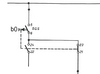
This thing is mounted in a facility, probably built in the 70's (drawings are from late 70's).
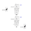
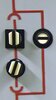
Thing is - the first atachment, as I read it - seems to make use of uneccesary poles of the switch - the 21-23 seems to have no rational function (never will be a closed current path between terminal 5-21).
Unless there is some delay function - maybe spring loaded - between different set of poles.
I'd be crazy happy if ther exist some sort of datasheet that can explain this")
Thanks in advance.
This thing is mounted in a facility, probably built in the 70's (drawings are from late 70's).
Thing is - the first atachment, as I read it - seems to make use of uneccesary poles of the switch - the 21-23 seems to have no rational function (never will be a closed current path between terminal 5-21).
Unless there is some delay function - maybe spring loaded - between different set of poles.
I'd be crazy happy if ther exist some sort of datasheet that can explain this
Thanks in advance.