Continue to Site

Welcome to our site!

Electro Tech is an online community (with over 170,000 members) who enjoy talking about and building electronic circuits, projects and gadgets. To participate you need to register. Registration is free. Click here to register now.

  • Welcome to our site! Electro Tech is an online community (with over 170,000 members) who enjoy talking about and building electronic circuits, projects and gadgets. To participate you need to register. Registration is free. Click here to register now.

Need TTL Cookbook page 171 & 172. 555 timer 2N3055 vintage Electric Fence Charger

Status
Not open for further replies.
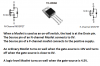
Where did you make that up from? - it's certainly no where near that high.

1500 ohms does seem high. I tested the coil again with both digital meters and got 1.4 ohms on both meters. Math works out to 9a on 12.6v. The mosfet is rated 9a I need to use a different mosfet.
 
I changed the circuit. LED on pin 3 shows the 555 is flashing at a rate of 1 time per second.

The 12v light bulb shows mosfet is ON and never turns OFF.?

100_3075.JPG
 
Why did you connect the N-MOSFET upside-down instead of to ground, as it was before? :confused:
It won't work that way, as the substrate diode will conduct and the transistor can't be turned off.
The source (pin 3) should be connected to ground.
 
Why did you connect the N-MOSFET upside-down instead of to ground, as it was before? :confused:
It won't work that way, as the substrate diode will conduct and the transistor can't be turned off.
The source (pin 3) should be connected to ground.

LOL numbers are right. I drew it wrong. I fixed it. See new drawing. 2N3055 transistor works good like this but not the mosfet.? I added a .1 uf cap to pin 1 to keep DC out of the mosfet but that did not help, mosfet is still ON all the time.

100_3077.JPG
 
Last edited:
Assuming a P-mosfet: Can't find the data sheet.
G-S connect a small diose. 1N4148.
Connect a 1meg to 100k resistor G-S.
I don't know why you can't drive the gate direct. But if you need to AC drive the gate you need a resistor and diode to reset the pulse.
1555273450331.png
 
Assuming a P-mosfet: Can't find the data sheet.
G-S connect a small diose. 1N4148.
Connect a 1meg to 100k resistor G-S.
I don't know why you can't drive the gate direct. But if you need to AC drive the gate you need a resistor and diode to reset the pulse.
View attachment 117696


I tried this on the work bench with a new mosfet right out of the package.
I shorted all 3 leads then tested it there is max resistance between pin 2 & 3 mosfet is OFF.
I put VOM + lead on pin 1 and - lead on pin 3 the mosfet turns ON.
When I put diode across pin 1 & 3 with - on pin 3 mosfet turns off.
When I put diode across pin 1 & 2 with - on pin 2 mosfet turns off.
Makes no difference if pins 1 & 2 are shorted or pins 1 & 3 are shorter mosfet still turns OFF.

Now that I have proven this works with - side of diode on pin 3 and + on pin 1 I soldered the diode across the mosfet on the circuit board and the mosfet stays ON.

Then I added a 150K resistor in parallel with the diode mosfet stays ON.

I tried several resistors from 2K to 1M and several different diodes on pin 1 & 3 also pin 1 & 2 mosfets stays ON.

It works on the work bench but not in the circuit.
 
Last edited:
Foun it.
Look at post #84, bottom left. High for 0.1 sec, low for 2 sec. This is a P fet. Pulling down turns it on! So you have it on most of ith time and off for 1/10 sec. The bulb will not cool down that fast. It will appear to be 100% on when it is actually off 5% off. 95% on. Slow bulb.
 
You keep adding schematics with more errors:
1) The P55NF06L Mosfet is N-channel and you have it in a P-channel circuit. In addition to the diode in it (shown on the datasheet that you should always copy) its gate is DC-floating so the Mosfet part never turns off and the diode always conducts.
 

Attachments

  • Mosfet.png
    Mosfet.png
    85.2 KB · Views: 83
You keep adding schematics with more errors:
1) The P55NF06L Mosfet is N-channel and you have it in a P-channel circuit. In addition to the diode in it (shown on the datasheet that you should always copy) its gate is DC-floating so the Mosfet part never turns off and the diode always conducts.

I looked online the difference between P channel & N channel it looks like load is on pin 3 for N channel and load is on pin 2 for P channel but both have B+ voltage on pin 3. I don't understand there is any difference? Just because I swapped places with the ignition coil and mosfet that makes it P channel instead of N channel? I don't see how the circuit has changed when 2 parts swap places. What if I had a circuit with a resistor & capacitor in series will it make any difference if resistor or capacitor is on the B+ side? If I swap coil & mosfet again then it becomes N channel again, how can that be? It is very easy for me to swap 2 wires on the circuit board and make this N channel again.

I though it was easier to draw circuit with 2 parts swapped. Here is N channel again. Will this actually make the circuit work? Truth is I actually have the circuit wired like this on the circuit board. I drew it with mosfet & coil swapped because it seemed easier to draw on the old drawing where many changed had been made the drawing was messy. Circuit does not work light stays on all the time. Today I decided to use a light bulb instead of the coil it is much easier to see if it works and what it is actually doing.

100_3082.JPG
 
Last edited:
Gary, your knowledge of Mosfets is completely wrong and backwards.
The load for a Mosfet used as a switch is almost always on its drain pin #2.

Again, you are showing an N-channel Mosfet upside down but you sketched its diode with the correct polarity. Its source pin #3 should be at ground and its load should be between its drain pin #2 and the positive supply.
Please learn these things:
 

Attachments

  • Mosfet details.png
    Mosfet details.png
    32 KB · Views: 77
Gary, your knowledge of Mosfets is completely wrong and backwards.
The load for a Mosfet used as a switch is almost always on its drain pin #2.

Again, you are showing an N-channel Mosfet upside down but you sketched its diode with the correct polarity. Its source pin #3 should be at ground and its load should be between its drain pin #2 and the positive supply.
Please learn these things:

So thats whats wrong the mosfet is connected backwards. I should have known that I been working with mosfets for several years on induction heaters I know heat sink tab is pin 2 and that is the output. I am brain dead just did not think about it.
 
Last edited:
I finished the PC board today and tested it. It works perfect except for 1 problem the mosfet over heats in about 15 seconds. With R6 = .5 ohms I get a 3/8" spark. With R6 = 1 ohm I get a very hot blue 3/4" long spark. With R6 = 2 ohms I get a weak 3/4" spark. With R6 = 3 ohms I get a very weak 1/4" long spark. 1 ohm limits current to 6.3a. The mosfet should be OFF 99% of the time. I have no scope, using the volt meter and adjusting R5 for the shortest time the meter will read a voltage pulse of 3v, if I shorten the pulse it is too fast for the meter to read it, meter shows 0v but ignition coil gives a very good spark. R4 time between pulses from 1 sec to 2 sec . With 2 sec between pulses and .1 pulse length mosfet over heats too hot too touch in 15 seconds. What is the problem? Is the mosfet not turning completely OFF? Look at the blue spark on pic #4. R6 = 2W resistor or 15w resistors both over heat.
I'm sorry, I don't understand how long a pulse is that shows 3v on a volt meter.

You've been dabbling in electronics for how many years, with no scope to show you what's really going on inside?

I know you've been doing tesla coils, inverters, 555 and other timers, etc. All of which you really need an oscilloscope to truly understand how the different parts of the circuit work together in the time domain to make it all work. And, when something isn't working, it helps you find the problem much faster.

I expect that if you had spent a couple hundred for even a cheep scope a few years ago, it would have paid for itself by now considering all of the blown mosfets you've gone through on your inverters.

More importantly though, you probably would have had the higher power inverter that you've wanted that actually worked.
 
I removed the mosfet and tested it. It tests good. I compared it to a brand new mosfet they both test the same. Here is the circuit. I have 12V brake like bulb from my vehicle in place of the ignition coil so I can see if it goes on/off. I plugged in the power supply the LED light on pin 3 of the 555 flashes ON for .1 second then goes off at a rate of 1 time per second. The 12V light bulb stays on. I notice when tested the mosfet it will turn off when pin 1 is shorted to pin 2 or pin 3 so I connect a diode to pin 1 and 3 light stays on. Then I connected diode from pin 1 and 2 light bulb stays on. Mosfet is not turning off.

When I test a mosfet on the work bench I notice once it is turned ON i can return 2 days later and it is still ON. I think once the mosfet in this circuit is ON it will stay ON until something turns it OFF. Disconnecting the wire on pin 1 will not turn it OFF. If I connect a 12V relay in parallel with the coil the relay will short pin 1 to pin 3 and turn the mosfet OFF every time the 555 pulses again.

100_3086.JPG
 
Last edited:
The Mosfet has a gate which draws no current and it has capacitance that holds the voltage until something grounds it which turns it off until something gives the gate 7V or more to turn it on.
The datasheet of the Mosfet shows that it turns off if its gate is driven to less than 2V.
The datasheet of a 555 shows that its ouput low is 0.1V which of course is less than 2V so the Mosfet should turn off.
Measure the voltage at the gate of the Mosfet to see if the 555 drives it down to 0.1V.

Which is defective, the Mosfet or the 555? Replace each one to see.

I replaced the 555 with a new one. I replaced the mosfet with a new higher amp one. My meter has a hard time reading max voltage with such a quick pulse meter reads in the 10V 12Vdc range. Same problem with low voltage the meter reads in the 4V 6V range when LED is off. Meter does not have time to lock on a specific voltage. The LED on pin 3 of the 555 goes completely OFF between pulses I have it set slow 2 seconds between pulses.

I did this experiment. I soldered an on/off switch from pin 3 of the 555 to pin 1 of the mosfet with circuit running the light stays ON. When I turn switch S1 off the light stays ON. With 12.6vdc still on the mosfet I shorted pin 1 to pin 2 the mosfet will not turn off. With PS off mosfet tests good.
With mosfet OFF and PS ON and S1 open light is not ON until I close S1. With S1 open light stays ON. I tried several different mosfets and I get the same results with IFR630, IFR640, IRFP460, and several others. With no heat sink on the mosfet once it turns ON it over heats and burns up quick if I don't get the PS off with in 5 to 10 seconds. Once a mosfet is ON none of them will turn off until the PS is turned off first. With S1 open and PS on light does not come ON until I close and open S1 and light stays ON with S1 open. Once light is ON and PS is ON mosfet can not be turned off by sorting the mosfet pins together. PS transformer is rated 10a but with a direct short it can probably pull 30 or 40 amps for a short time but light bulb will limit the current. I'm not sure what amp rating is on the brake light bulb probably less than 10a vehicle wires are smaller that 14 gauge probably closer to 18 gauge. Good thing I have an assortment of mosfets from old TVs they all say ON once S1 turns them ON, brand new mosfets do the same thing.

100_3087.JPG
 
Last edited:
Of course a Mosfet should turn off if its gate pin1 is connected to the source pin3 by the 555 or by a switch. When your Mosfet does not turn off then it is destroyed.

The maximum allowed gate voltage for your Mosfet is only 16V. Since you are disconnecting the gate then the last high voltage pulse can feed through the air and zap the extremely high resistance of the gate.

Never disconnect the gate of a Mosfet because then stray static electricity from you can also zap the gate.
 
Even with the 555 pin 3 connection, shouldn't there still be a gate to source(ground) resistor present? To keep the gate at a known level and to remove any stray/spurious levels on the gate?

And if the coil being used is one of the old round ones used before the advent of HEI type ignitions, you do know it's rated for 6V even though they were in a 12V system. The only time those coils saw 12V was while the engine was cranking over, after starting they had a ballast resistor to run at ~ 6V.
 
Of course a Mosfet should turn off if its gate pin1 is connected to the source pin3 by the 555 or by a switch. When your Mosfet does not turn off then it is destroyed.

The maximum allowed gate voltage for your Mosfet is only 16V. Since you are disconnecting the gate then the last high voltage pulse can feed through the air and zap the extremely high resistance of the gate.

Never disconnect the gate of a Mosfet because then stray static electricity from you can also zap the gate.

I can make all the mosfets turn off if I turn the PS off. Short pin 1 to pin 2 or short pin 1 to pin 3. Mosfet turns off so I turn PS on and with switch S1 open the 555 circuit runs and the LED flashes but the light bulb stays OFF. Soon as I close S1 light comes ON and stays ON until PS is turned off.
 
Even with the 555 pin 3 connection, shouldn't there still be a gate to source(ground) resistor present? To keep the gate at a known level and to remove any stray/spurious levels on the gate?

And if the coil being used is one of the old round ones used before the advent of HEI type ignitions, you do know it's rated for 6V even though they were in a 12V system. The only time those coils saw 12V was while the engine was cranking over, after starting they had a ballast resistor to run at ~ 6V.

Discontinuing 6V electric systems on vehicles started in 1953 by 1955 12V was the national standard. There is no resistor on 12V ignition coils. There were after market resistors for people that converted an old 6V systems to 12V so you can use the 6V coil on 12V but people soon learned it was best to have no 6V parts in a 12V system. My 1967 Chevy is 12V with a 12V coil factory original it says 12V on the side of the coil and there is no resistor. The ignition coil I was using on this 555 project is 12V but now I am using a light bulb.

mytruck.jpg
 
Yes, the gate of the Mosfet should have a resistor to ground to protect it from being zapped by nearby static electricity when power for the 555 is turned off. 27k should do it.
 
Status
Not open for further replies.

Latest threads

New Articles From Microcontroller Tips

Back
Top