1) The LED connected to the base of the transistor will never produce any light, because the base-emitter turned on voltage will be only 1V.
2) The 100 ohms base resistor has 9V across it (if you have an original 555) which is a current of 90mA. With this fairly low base current the 2N3055 saturates with an output current of only 900mA.
3) The 100nF capacitor with your resistor values produces very short duration pulses and pauses. 8us and 200us.
4) The timing resistors are backwards producing 200us output current and 8us pauses between output current.
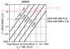
5) The datasheet for the LM555 shows 20uF with a 10k resistor for a 0.1 second pulse and about 330uF with 280k for 1 second pauses.
You talk about "555" ICs but you do not say if they are the original powerful NE555, LM555 or the weak Cmos LMC555, TLC555 and ICM7555.