Continue to Site

Welcome to our site!

Electro Tech is an online community (with over 170,000 members) who enjoy talking about and building electronic circuits, projects and gadgets. To participate you need to register. Registration is free. Click here to register now.

  • Welcome to our site! Electro Tech is an online community (with over 170,000 members) who enjoy talking about and building electronic circuits, projects and gadgets. To participate you need to register. Registration is free. Click here to register now.

Need TTL Cookbook page 171 & 172. 555 timer 2N3055 vintage Electric Fence Charger

Status
Not open for further replies.
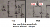
Here's the LTspice simulation of AK's 555 circuit in post #9 with fixed resistors to give the desired duty-cycle of 0.1s ON with a 2s period:

I did not understand how you got these numbers when I saw this for the first time and numbers did not work in the book formula, but now I do. Book formulas don't work with parallel resistors. This is an interesting way to do this.


View attachment 117253

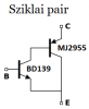
Edit: Below's a modified circuit with only one diode.
The main advantage is that the timing circuit is not connected to the output, as in the above circuit, so any output loading has no effect on the timing.

View attachment 117256
 
Your latest circuit will zap the 2N3055 when it turns off because there is nothing to arrest the high voltage flyback spike. A Zener diode is needed from the collector of the transistor to ground.

Your 10V transformer produces a peak voltage of 14.14V. The rectifier bridge reduces it to about 12.5V. If the electricity is 115VAC instead of 120VAC then the input to the 7812 is much too low for it to produce 12V output, it needs an input of at least 14V or 15V. Why not use a 12V transformer?

Your 100 ohms base resistor reduces the base current to about 90mA then the output current into the ignition coil will be only about 900mA.

I wish you can see that a pot is simply two resistors in series like this:
 

Attachments

  • NE555 with PWM pot.png
    NE555 with PWM pot.png
    220.9 KB · Views: 105
Your latest circuit will zap the 2N3055 when it turns off because there is nothing to arrest the high voltage flyback spike. A Zener diode is needed from the collector of the transistor to ground.

Your 10V transformer produces a peak voltage of 14.14V. The rectifier bridge reduces it to about 12.5V. If the electricity is 115VAC instead of 120VAC then the input to the 7812 is much too low for it to produce 12V output, it needs an input of at least 14V or 15V. Why not use a 12V transformer?

Your 100 ohms base resistor reduces the base current to about 90mA then the output current into the ignition coil will be only about 900mA.

I wish you can see that a pot is simply two resistors in series like this:


Last time I checked wall voltage was 121 vac. I will build power supply first to see what the voltage turns out to be then I know what to do next. I had a 1N4007 diode across 2N3055 collector to ground but someone said, get it off there that won't work. I found an electric fence circuit online with 1N4007 on the 2N3055 collector it said exactly what you said, it protects the transistor from HV death. I don't have any zener diodes, never did, never worked with them, I know nothing about them, don't know which 1 to order?

I have a 555 driving a 2N3055 with no base resistor I built 30 years ago. The 555 has a variable resistor for 1Hz to 30KHz. Ignition coil makes a 3/8" spark about 10mm at low Hz. As Hz is turned up spark gets shorter and shorter finally no spark above 10KHz ignition coil is not a high Hz device. No base resistor and no diode on collector to ground it has been working 30 years. It has an 8vdc power supply because that is all I had at the time to build it with. Since I can't find any of my other 2N3055 transistors I will probably use parts from old circuit to build the new circuit.

I recall reading voltage has to be 2 volts higher than 7812 for it to work. That might be a problem.

I don't have a 12v transformer. 10v is the closest thing i have.
 
Last edited:
I recall reading voltage has to be 2 volts higher than 7812 for it to work. That might be a problem.

I don't have a 12v transformer. 10v is the closest thing i have.

If your gonna use a 10vac output transformer, then there's no point using a 12 volt regulator because it wont regulate. I showed back on post #40 why you need something larger than 10vac output transformer.

eT
 
If your gonna use a 10vac output transformer, then there's no point using a 12 volt regulator because it wont regulate. I showed back on post #40 why you need something larger than 10vac output transformer.

eT

With a transformer, bridge rectifier and 3300uf cap, the digital meter reads 16.4 vdc. Transformer must be 12vac not 10 vac like I thought.
 
Last edited:
The unregulated 16.4V will drop when loaded.

Before, yours and other fence circuits had the output diode to prevent negative voltages that will never happen. The flyback voltage spike is positive, not negative since the transistor drives the bottom end of the coil to ground. When the transistor turns off the coil drives its collector to hundreds of volts positive. An ordinary diode can clamp the positive voltage spike to the positive supply and mess up the supply voltage but a Zener diode will clamp the spike to a reasonable voltage above ground instead.

The NE555 maximum allowed output current is only 200mA. Since the 2N3055 transistor produces a saturated output 10 times its base current then you can reduce the 100 ohms series base resistor to 39 ohms for a coil current pulse of about 2A.
 
With 9900uf capacitor on the transformer with bridge rectifier output voltage has gone up from 16.4 to 17.1 volts DC that will be a 5v drop for the 7812.

Which zener diode do I need?
 
Last edited:
Hello,

I've replaced the 2N3055 with a Mosfet per post #73 as it does solve the BJT base current issue. R7 Limits the current on the main power supply. I'm not sure about the Zener but I think max VDS is about 60v.

eT

1553482934152.png
 
Last edited:
I've added a Darlington driver to drive the 2N3055 harder.

If you're adding a driver, don't add it like that - there's too little voltage at the collector of the 2N3055 when it's turned ON to provide good base drive - the same actually applies to the internal connections of the darlington as well. Feed Q1 collector from the positive rail via a lowish resistor, so you have plenty of base drive current for the 2N3055.

Other ways of doing the driver could easily improve it further.
 
I would use a Sziklai pair with its current gain of at least 100 times and low voltage drop like this:
 

Attachments

  • Sziklai pair.png
    Sziklai pair.png
    5.8 KB · Views: 101
If you're adding a driver, don't add it like that - there's too little voltage at the collector of the 2N3055 when it's turned ON to provide good base drive - the same actually applies to the internal connections of the darlington as well. Feed Q1 collector from the positive rail via a lowish resistor, so you have plenty of base drive current for the 2N3055.

Other ways of doing the driver could easily improve it further.

I just replaced the BJT's with a mosfet per post #73.
 
Last edited:
Is it possible to use a mosfet instead of the 2N3055 I have lots of mosfets and heat sinks for them too plus wiring will be easier?
 
I finished the PC board today and tested it. It works perfect except for 1 problem the mosfet over heats in about 15 seconds. With R6 = .5 ohms I get a 3/8" spark. With R6 = 1 ohm I get a very hot blue 3/4" long spark. With R6 = 2 ohms I get a weak 3/4" spark. With R6 = 3 ohms I get a very weak 1/4" long spark. 1 ohm limits current to 6.3a. The mosfet should be OFF 99% of the time. I have no scope, using the volt meter and adjusting R5 for the shortest time the meter will read a voltage pulse of 3v, if I shorten the pulse it is too fast for the meter to read it, meter shows 0v but ignition coil gives a very good spark. R4 time between pulses from 1 sec to 2 sec . With 2 sec between pulses and .1 pulse length mosfet over heats too hot too touch in 15 seconds. What is the problem? Is the mosfet not turning completely OFF? Look at the blue spark on pic #4. R6 = 2W resistor or 15w resistors both over heat.

100_3070.JPG


100_3065.JPG


100_3068.JPG


100_3069.JPG
 
Last edited:
For what you are doing, I don't think there is any need for R7.

Separate from that, the bipolar NE555 output stage does not go all the way to GND. Probably not the problem, but to test the theory I would leave R7 where it is, increase it to 100 ohms, and add a 1.0K resistor from the gate to GND. This will decrease the gate drive slightly, but it still will be near 10 V. AND, it lowers the off state gate voltage by 10% ish.

Now that I've looked up the IRF630, it smells like a culprit. At 6.3 A drain current, that's 11.5 W. You may need something more accurate than a volt meter to see your true on-time.

The worst-case duty cycle is approx. 5K / 150K; 3.33%, or a 96.7% off time. Move either pot off its end stop and the off time percentage decreases.

Nice, clean assembly. Gold star.

ak
 
Last edited:
Assuming your PS can indeed supply 10A, look at the basic Ohms laws. With a 2 ohm resistor (assume that is the only resistance), you will be drawing close to 6A current. I^2xR = 6x6x2 = 72 Watts of power thru the resistor. With a 10% duty cycle (1sec off, 0.1 sec on), that still means 7.2W of heat. The MOSFET is on for approx. 10% of the time, off for 90%.
Of course, things like RDSon of 0.4 ohms changes things (12V/2.4) = 5A = 50W x10% = 5W on resistor. 5A thru the MOSFET would be 5x5x0.4 = 10W dissipation for the MOSFET, which may require a larger heatsink.
Lower resistances to the coil just compound the heat issue even more. Not sure about the resistance of the coil itself.

I agree with Analogkid, put a 1k (or 1 to 10k) resistor from gate to ground to ensure the gate does go down low when off. With heavy current draw in pulses, it may also be possible you are dropping the voltage source on the 555 (ie the entire power supply), causing some "reset". This depends on the capacity of the transformer of course. Try a larger resistor to the coil, see if the heat dissipation drops (even though the spark may be a lot smaller). Measure the voltage supply to the 555 and at the gate of the MOSFET with a high value resistor, then again with a 2 or 1 ohm. The readings should be about the same if you are not overloading the transformer. On an "average", the MOSFET gate voltage should be well below 10V, even lower than 5V with a regular meter (which cannot read spikes). Only with a scope can you really see what is happening however....
 
Ignore everthing I said there was an Idiot wiring mistake an the coil actually works like that.

I changed R7 to 100 ohms then added the 1K resistor and it does not work. Now I realize the ignition coil was connected wrong across pin 2 and 3 of the mosfet before but now it is connected the correct way and nothing works. I removed the 1k resistor and replaced the 40 ohm resistor it still does not work wired the correct way. I tested all the parts mosfet is good, voltages are good, every thing work but no sparks. The ignition coil ohms 1.5K ohms. Now I see the way it was before when it worked is like this circuit below. There is 12.6v to the ignition coil all the time when the mosfet turns ON is shorts out the coil and there is a big spark. No wonder mosfet was getting hot it is a direct short across the power supply. When mosfet turns ON it shorts out the coil and this fires a big spark. Now I have it connected the correct way it does not work maybe because .1 second is too short to fire the coil? Ignition points in a car are closed all the time, when cam opens the points at the correct time it fires. Now I need to experiment change pulse from .1 second to a larger number to find out what works.


100_3072.JPG
 
Last edited:
With the last schematic, you would have to program the MOSFET to be on 90%, and off 10% of the time to get a pulse to the coil (based on your cam logic). Otherwise, the coil is conduction most of the time, and you just short it 10% of the time. Get the "story" straight, which is it supposed to be - 10% on or 10% off for the MOSFET? Reversing the logic to match a cam, you would have to reverse the on/off times with the two potentiometers.
The MOSFET with a 1 ohm resistor would have a total of 1+0.4RDSon = 1.4 ohms resistance total when in conduction. That would draw about 8-9 amps. That would be 9x9x0.4 = 32W for the mosfet while conducting, and adjust for conduction time %.

Wire resistance of the ignition coil is 1500 ohms. Add the 1 ohm resistor you get 1501 ohms. The ignition coil is not induction to DC volts its just DC wire resistance plus the resistor. But do the math 12.6 / 1501 = .0083 amps. How can amps that low heat the 2W resistor smoking hot the the mosfet too hot to touch in 15 seconds. It makes no difference how I just need to fix it and get it right. Tomorrow is another day. I'm going to check see what the dumbest show on TV has ON tonight, Svengoolie says, Son of Dr Jekyll. LOL. 90% of these shows are too stupid to watch but much better that most crap on TV these days. The Giant Spider that ate New York City was interesting. LOL
 
Status
Not open for further replies.

Latest threads

New Articles From Microcontroller Tips

Back
Top