Continue to Site

Welcome to our site!

Electro Tech is an online community (with over 170,000 members) who enjoy talking about and building electronic circuits, projects and gadgets. To participate you need to register. Registration is free. Click here to register now.

  • Welcome to our site! Electro Tech is an online community (with over 170,000 members) who enjoy talking about and building electronic circuits, projects and gadgets. To participate you need to register. Registration is free. Click here to register now.

Need help with Circuit

Status
Not open for further replies.

ZTatZAU

Member
Hello, this is my first post on the forum. Sorry it's so long!

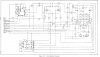
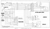
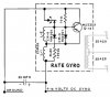
I need some help to better understand the circuit shown below. This circuit shown is only a portion of the entire schematic for the device.

**broken link removed**

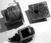
This circuit drives a gimble mounted rotor (Gyroscope) in a coil wrapped cylindrical housing via an optical sensor located on the PCB attached to the open end of the housing. (See photo below)

**broken link removed**

I'm pretty sure the optical sensor is depicted by the "curved double-headed arrow" in the upper left of the schematic. If I am correct, the sensor is essentially a switch that opens and closes as it "sees" the "dark and light" hemispheres of the rotor going by. Does this make sense? If so, can anyone explain the current path through the circuit as the "switch" opens and closes?

Also... Is the coil simply turned on and off or does the circuit actually reverse the bias of the coil as the "switch" opens and closes? I am puzzled as "physically" there is only one coil with only two leads (see photo) whereas the schematic shows two coils (L1 & L2) with three connections. I'm guessing the real coil is represented in the schematic as L1 & L2 combined; Or, L1 and L2 each represent the same coil in different states. Can anyone clear this up.

Lastly... Currently, when power is applied to the circuit, the rotor starts to turn but only turns one half of a complete revolution and then stops. So whatever is suppossed to change the bias of the coil is not working. I have tested the optical sensor with the PCB disconnected by applying 14V to the input of the board and then, while alternately lighting and shading the sensor, measured the board's output to the coil. In this test, the output to the coil starts at about 6V and drops to zero (or close to zero) as the sensor is lit or shaded. So I am pretty confident the sensor is working as it should. What other components in the circuit shown, if failed, might likely cause this behavior?

Any assistance will be much appreciated.
ZT
 

Attachments

  • RateGyroCircuitPost.jpg
    RateGyroCircuitPost.jpg
    38 KB · Views: 159
  • GyroRotor&Housing.jpg
    GyroRotor&Housing.jpg
    91.7 KB · Views: 236
Last edited:
From the back of that circuit board, it appears to contain more components than your schematic shows.
 
I should have mentioned...

Hi Duffy,
I should have mentioned that this circuit is only a portion of a larger schematic.

I could be wrong but I'm pretty sure the portion I've shown is what it takes to spin the gyro rotor which is all I'm concerned about at this point.

I'd be happy to post the entire schematic if you think there are other considerations.

I appreciate your reply!
ZT
 
Last edited:
Last edited by ZTatZAU; Yesterday at 02:23 PM.. Reason: Add images and clarity to post

Doesn't look like you added any images, those are the same as before. You did manage to edit the post to now mention that this is an INCOMPLETE schematic, which I had already figured out after spending time looking at it, trying to see how I could help you with it.
 
Doesn't look like you added any images, those are the same as before. You did manage to edit the post to now mention that this is an INCOMPLETE schematic, which I had already figured out after spending time looking at it, trying to see how I could help you with it.

Hi Duffy!
I'm no electronics expert and as I noted, this is my first post on the forum and I don't want to get off on the wrong foot. So don't get me wrong here but after reading your first reply, I edited my initial post to note that this was only a portion of a larger schematic AND, after seeing how others included images with their posts (as opposed to attaching thumbnails), I added the circuit and photo to the body of my post so as to make them more convenient for others to view right along with the text.

Yes, there is more to this device than the portion that I've shown, but all that depends on first getting the gyro to spin which is all I am currently trying to accomplish.

I also replied directly to you; thanked you for your reply, and stated... "I could be wrong but I'm pretty sure the portion I've shown is what it takes to spin the gyro rotor which is all I'm concerned about at this point." adding... "I'd be happy to post the entire schematic if you think there are other considerations." Again I could be all wrong on this but it would have been nice and a bit more informative had you addressed this in your last reply.

I appreciate any time you may have spent and any assistance that you or others may be able to provide. That, after all, was the reason I posted here.

BTW Duffy! Have you been able to figure out and explain what happens in this portion of the circuit, (assuming 14V power and ground are supplied where shown), when the sensor switch (double headed curved arrow, if that's what it is), opens and closes?

Thanks again for any and all help on this project! ZT
 
Have you been able to figure out and explain what happens in this portion of the circuit, (assuming 14V power and ground are supplied where shown), when the sensor switch (double headed curved arrow, if that's what it is...

I've been able to figure out that you still have not posted the schematic, and we are now several posts into this.
 
Comm'on Duff

Why didn't you just ask when I said I'd be happy to post the entire schematic if you thought it would help or was relevant to getting the gyro to spin?

A copy large enough to read will probably be too big to fit in the body of this post so I'll upload a larger version for you to click on. Thanks for your help!

I look forward to any or all replies. ZT
 

Attachments

  • GyroAmpSchematic23x13x72dpi.jpg
    GyroAmpSchematic23x13x72dpi.jpg
    336.7 KB · Views: 217
*sigh* Just as I suspected - you don't have the right schematic.

But you knew that, didn't you? That's why you went through all this BS instead of posting the rest of your schematic. That's why you still have not posted a pic of the top of the board.
 
Huhhh?

WT....? You're real a trip Duffy! I'm not trying to hide anything nor am I trying fool anyone. But then you're the electronics expert who can conjure up secret agendas and ascribe ulterior motives to a guy who's simply looking for some help in understanding the electronics portion of an electro-mechanical device that I'm trying to get running!

I've tried to be cordial, courteous, and thorough in everything I've written so as not to overstep the bounds of a noobie here but so far all you've displayed to me is rudeness, arrogance, and a know-it-all attitude.
YOU WANNA' HELP? THEN HELP - BUT CUT THE CRAP! TALK ABOUT BS!!!

The reason I only included a portion of the schematic was because that's the portion of the circuit that I thought drove the gyroscope... NOT BECAUSE I WANTED TO HIDE the rest of the circuit! Likewise, I posted a picture of the bottom of the board simply to show the gyro, gyro housing, and photo sensor... NOT BECAUSE I WANTED TO HIDE the other side of the board!

You wanna' see the top of the board? All you gotta' do is ask! Again I'm not trying to trick anybody!

**broken link removed**

Now please allow me to answer the single question you've ever posed to me amid your littany of pompous observations, self-serving aggrandizing statements, and most recently, your presumably psychic but seriously mistaken accusations. Namely, " *sigh* Just as I suspected - you don't have the right schematic... But you knew that, didn't you? That's why you went through all this BS instead of posting the rest of your schematic. That's why you still have not posted a pic of the top of the board"

My answer is NO and your accusitory and insulting remarks are uncalled for! If indeed it's not the correct schematic, it's not because I'm trying to hoodwink anyone, but rather a case of my lacking the expertise to have made that determination.

What I do know is that I have long searched for and over some period of time obtained most of the major components of this system and a few spare parts, as well as the supposedly applicable factory service manual from which the schematic that I posted came from. Of course a novice such as myself can only rely on the published title of the manual, the unit part numbers of the pieces I have; and compare them to the matching part numbers, diagrams and descriptions contained in the manual. But what do I know? While I have discovered what appears to be some minor revisions during the time this system was produced, I do believe the overall circuitry to have basically remained unchanged.

For example, the photo below shows a slightly different version of the gyro mounted circuit board shown above. Same part number but apparently a slightly different revision. While the above circuit board has a miniature lamp to help illuminate what the optical sensor sees, the version of the same board below omits the light bulb and uses a slightly different sensor.

**broken link removed**

Other variations, I've found, are the result of some of the older style semiconductors and paper capacitors that were in these old boxes, being replaced in the field with more recent and more reliable components.

So why am I posting all this? It would be easy to say it's because I still need help with the electronics but frankly that's no more important to me at this point than letting you know that I resent your demeaning attitude and your unfounded allegations that I have somehow been deliberately deceptive and less than forthcoming in this thread. THAT"S BS and I assure you it is not the case! Now, to be fair to you, it may be that you haven't yet realized that this little circuit board is only a small portion of the entire circuitry and the bulk of the components shown on the schematic are located on another circuit board. But hey! How would you know? Since I didn't mention that either. Perhaps the following pictures will help you step back and pull your head out where it seems to be stuck. I'm trying to be nice here!

From the service manual...

**broken link removed**

And a couple of the GyroAmps I have for parts...

**broken link removed**

And the one I'm working on with the cover removed...

**broken link removed**

And two close-up views of the GyroAmp Assembly for a better look...

**broken link removed**

Here you can see (in the photo on the right) the small inductor coils that Iwere grayed out on my original "incomplete schematic" because I believed they were not relevant to spinning the gyro but rather related to gyro output signals. You may also be able spot the four exterior power transistors that are shown in the right hand - lower center of the schematic, and the brown adjusting wheel of the 10K pot that is used for system centering adjustments (upper left of the left hand photo). You may even recognize what constitutes the mixer amp and oscillator sections on the large circuit board though I sure can't at this stage of the game. The point is, and again I could be wrong, that much of the full schematic, (perhaps with the exception of the oscillator section), is unrelated to the spinning of the gyro and more to do with the proper output signals to a servo motor. Please try to keep in mind that I am only trying to get the gyro to spin at this time.

So my question at this point, if your still with me, is "Do you really still believe that I have the wrong schematic for this device?" If so please explain why?

Otherwise, If you now believe the schematic I posted might be the correct one after all, I'd appreciate some help in understanding what part of this circuit actually energizes, pulses, or reverses the bias of the coil that spins the gyro?

ZT

PS: Just so you have everything that I do, I've also uploaded copy of the system harness schematic which may help with an overall view of the entire system. I think it will be too large to include in the post.
 

Attachments

  • HarnessSchematic.jpg
    HarnessSchematic.jpg
    319.4 KB · Views: 175
As far as the principle of operation of the rotor ....what makes it rotate ....I am guessing that the inductors L-1 and L-2 generate a time-varying, or increasing magnetic flux vector, when the switch is closed. Then, when the switch is open, the PNP transistor is turned on and the flux vector in L-2 is reversed, and cancels out the flux vector of L-1, for a half cycle or until the switch is closed again.

The resultant waveform for the overall flux vector within the coil assembly would then be some sort of sawtooth, or possibly an asymmetric triangular form.

If you have a list of the parts and their values, it would be of interest to know the specification values for L-1 and L-2. ... I would guess that L-2 has twice the value of L-1. ....

As far as getting the rotor to spin, the PNP transistor could be defective, or one of the diodes connected to its base might be shorted. You have said that you checked the opto-switch. It might be beneficial to confirm that it does conduct current .... without excessive resistance. ....

What do you think about de-soldering the PNP transistor, and checking it with a transistor tester? I think that I would want to make sure that the opto switch is working properly ....actually conducting current and switching states...

Another thought .... electrolytic capacitors ... i.e. the 35 µF part, are known to age and fail after some years of use. Can you de-solder that part, and check it with a capacitor tester?
 
Last edited:
NOW we're getting somewhere.

The motor coil looks like it's going to be driven off those 2N3055's, which are hooked in an "H-bridge" configuration, and THAT will reverse the polarity to the coil. (your original circuit was part of something completely different, I believe you will find it connected to one of those little transformers on the side)

The 2N3055 (the big transistors bolted to the case) is a fairly old bipolar that blows out a lot. It will often (especially in older equipment) simply have a corroded transistor socket or contact - I can see rust on the transistors themselves, good chance simple corrosion is causing the problem. A bad transistor or socket in the H-bridge can stop the reverse polarity, so this is a good starting point to work from if the motor coil isn't reversing. Do you know how to check a bipolar transistor with a meter?
 
Hello 88,

Thanks much for your thoughtful reply!
You've given me good food for thought and some good reasons to rethink some of my earlier assumptions. My understanding of basic electronics is rudimentary at best and I appreciate your help. I've quoted your comments below in bold 'cause I haven't yet got the hang of the forum's quote feature.

As far as the principle of operation of the rotor ....what makes it rotate ....I am guessing that the inductors L-1 and L-2 generate a time-varying, or increasing magnetic flux vector, when the switch is closed. Then, when the switch is open, the PNP transistor is turned on and the flux vector in L-2 is reversed, and cancels out the flux vector of L-1, for a half cycle or until the switch is closed again.
Do you think the "double headed curved arrow" just above L-2 actually represents the opto-switch? Or simply represent the rotation of the spinning rotor and the switch is depicted by the upward arrow just to the right of the double headed curved arrow? Either way do you agree this is the location of the opto-switch in the circuit? Assuming your guess is correct can you describe how the current flows though L-1 and L-2 and each branch of the circuit as the switch opens and closes and the transistor turns on and off?

If you have a list of the parts and their values, it would be of interest to know the specification values for L-1 and L-2. ... I would guess that L-2 has twice the value of L-1. ....
I have not been able to find any sort of parts list and many of the components that I can identify are no longer listed in the electronic supply house databases. This is a pretty old box. For instance the PNP transistor you mentioned is labeled on the schematic as MJ2253. The only MJ2253 I've been able to find is only available in a Type TO-66 case and I know there's none of those style cases in this device. Can you tell me what the inductors L-1 & L-2 might look like? Also many of the components on one of the boards I have, are marked with the script like Motorola "M" followed by three numbers. Some of these also have additional markings but nothing that I can find in the databases I've searched. Do you know of any database I can search online for a cross reference to these old (mid to late 1960's) Motorola 3 letter identifiers?

As far as getting the rotor to spin, the PNP transistor could be defective, or one of the diodes connected to its base might be shorted. You have said that you checked the opto-switch. It might be beneficial to confirm that it does connect current .... without excessive resistance. ....
I did check the opto switch rather primitively with a digital voltmeter and then tricked the switch into opening and closing with a small flashlight. The output to the gyro coil did cycle between 6v and 0v or close to it. I recently came by a nice oscilloscope and as soon as I learn how to use it, I will try to check the actual waveform. I will also follow your suggestion to check for current through the opto-switch and see what I find. How much resistance through the switch would you consider excessive? Anything more than an ohm or two? After doing so I will check the PNP transistor if I can locate it. The opto-switch and the PNP seem to be likely candidates because I think I'm only getting half of whatever should be happening.

I look forward to any and all replies. ZT
 
NOW we're getting somewhere.

The motor coil looks like it's going to be driven off those 2N3055's, which are hooked in an "H-bridge" configuration, and THAT will reverse the polarity to the coil. (your original circuit was part of something completely different, I believe you will find it connected to one of those little transformers on the side)

The 2N3055 (the big transistors bolted to the case) is a fairly old bipolar that blows out a lot. It will often (especially in older equipment) simply have a corroded transistor socket or contact - I can see rust on the transistors themselves, good chance simple corrosion is causing the problem. A bad transistor or socket in the H-bridge can stop the reverse polarity, so this is a good starting point to work from if the motor coil isn't reversing. Do you know how to check a bipolar transistor with a meter?

Thanks for your reply Duffy! And YES this IS more like it!

I don't know if it's the best way but I have checked the 2N3055's with a DMM on the Diode Setting. Then checking the resistance across each of the E-B-C junctions in both directions. Then comparing my readings to a chart I dug up that specifies Hi Resistance (open) and Low Resistance (an ohm or so) for each junction on a good PNP or NPN transistors. Using this method I found two of the transistors (Q-9 & Q-10) were bad. I replaced all four of them last evening and had high hopes for my next gyro function test after finding and replacing the little 6v lamp beside the sensor. (I'm using the green circuit board for now). Same bad results! The rotor turned 1/2 of a revolution and then stopped abruptly with each application of power.

I'm now thinking I should probably check at least Q-9 & Q-10 again thinking whatever took them out might have killed the new ones too!

While there was some corrosion on the transistors the case looked pretty clean underneath them. I simply reused the old thin plastic base "insulator gaskets" under the new transistors. Should I be using some sort of insulating grease instead or in addition to the "gaskets"?

I do appreciate your help! ZT
 
I simply reused the old thin plastic base "insulator gaskets" under the new transistors. Should I be using some sort of insulating grease instead or in addition to the "gaskets"?

Those thin plastic insulator gaskets are made from mica film and serve to electrically isolate the transistor from the heatsink. The insulating grease you refer to is thermally conductive paste and should be re-applied if the transistor is replaced.

EDIT: You did re-use the original mounting hardware too, didn't you? (Plastic insulating sleeves and washers.)
 
Last edited:
Those thin plastic insulator gaskets are made from mica film and serve to electrically isolate the transistor from the heatsink. The insulating grease you refer to is thermally conductive paste and should be re-applied if the transistor is replaced.

EDIT: You did re-use the original mounting hardware too, didn't you? (Plastic insulating sleeves and washers.)

Thanks for the info Mickster!

I will remount the 4 transistors with some conductive paste as you suggest. And yes, I was careful to reassemble all the hardware including the insulating sleeves and washers from where they came.

I appreciate the info and caution. ZT
 
Rotor Rotation ...

The rotor rotation is caused by a changing magnetic flux vector in the main L-1 and L-2 coils. These coils are the large wire coils that appear in your very first post. They would be wrapped co-axially around the outside of the rotor housing. There must be 3 leads coming from the two coils .... one from each end, and one center tap connection.

If you have only two leads, then one lead has broken off ... probably where you can't see it.

The current direction in coil L-1 would not change in direction. The current in L-2 would be the same as in L-1 for half a rotation cycle, and then would change or reverse direction for the other half cycle ... or switch position.

The notation of the switch on the first diagram that you posted does not give any indication that it is optical in nature. It just shows an open and close position, and might have been a mechanical switch of some sort in an earlier version of the gyro.

I am trying to determine which transistor in your photographs is Q-13 ... that is the MJ2253 PNP transistor. According to the available data sheets, it should be a relatively large TO-66 case .... roughly 1" long and 1/2" wide. .... probably mounted on the outside of the frame.
 
The motor coil looks like it's going to be driven off those 2N3055's, which are hooked in an "H-bridge" configuration, and THAT will reverse the polarity to the coil. (your original circuit was part of something completely different, I believe you will find it connected to one of those little transformers on the side)...QUOTE]

Hi Duff,
I reread your post and opinion on the function of the two pairs of 2N3055's and then got my head back into the device and the schematic. Despite your well stated analysis, I've come full circle back to my original hunch and believe that the spinning of the gyro has to be all right there in the little circuit I first posted.

I can't get away from the fact that power and ground comes into the green circuit board in only one spot (a direct connection to terminals A and B of the connector CD-46 on the harness diagram and displayed on the left side of the schematic) and the only connection to the 2 leads going to the gyro (motor) coil come directly from the little circuit board. There is simply no other connection either to or from the small circuit board. So I am again pretty sure that that is were I will find the problem. A bad transistor Q-13 or as User_88 suggested one of the diodes connected to its base.

I do think you're correct in that the paired transistors do indeed function to reverse polarity but I'm thinking that the polarity reversal is to run the servo motor in one direction or the other (steer left or steer right) through terminals J & K in connector CD-47.

If you have the time, please have another look at the drawings and consider the above and get back to me with your thoughts.
Thanks again for your help. ZT
 
The rotor rotation is caused by a changing magnetic flux vector in the main L-1 and L-2 coils. These coils are the large wire coils that appear in your very first post. They would be wrapped co-axially around the outside of the rotor housing. There must be 3 leads coming from the two coils .... one from each end, and one center tap connection.

If you have only two leads, then one lead has broken off ... probably where you can't see it.

The current direction in coil L-1 would not change in direction. The current in L-2 would be the same as in L-1 for half a rotation cycle, and then would change or reverse direction for the other half cycle ... or switch position.

The notation of the switch on the first diagram that you posted does not give any indication that it is optical in nature. It just shows an open and close position, and might have been a mechanical switch of some sort in an earlier version of the gyro.

I am trying to determine which transistor in your photographs is Q-13 ... that is the MJ2253 PNP transistor. According to the available data sheets, it should be a relatively large TO-66 case .... roughly 1" long and 1/2" wide. .... probably mounted on the outside of the frame.

Hi 88,
Thanks again for your reply. Much of my confusion comes from the pondering of whether L-1 and L-2 are in fact the gyro housing coil. The third lead problem has kept me stumped. There is only two leads coming out of coil unless the three coils I've looked at each have had one wire broken off. Three different samples and they all have only two leads. I am ready to accept that L-1 and L-2 do in fact depict the gyro coil winding and that brings me back to my theory that L1 and L2 are depict the one coil in its two different states.

I posted previously that I also found an MJ2253 but like you only in the TO-66 case style. I know what they are (sometimes referred to as Baby TO-3's) and there aren't any in this device. I did de-solder what I thought might be Q-13 to test it from one of the two boards I've been fooling with. It's marked M 639 - 2N5192 and is available in a SOT-32 Case. I will check the data sheets for each and though I'm not sure what all the values mean I should be able to find out if the two devices are electrically the same or similar. I will post again on that with my findings.

Thanks a lot for the great description of the current flow of the little circuit. That helps a lot with my visualization. The only thing I'm not clear on is what exactly depicts the switch. The little lead with the curved arrow running through it or the lille lead with the upward poining arrow? I am howver now quite sure this switch is the fact the opto-sensor.

I appreciate your interest and your assistance and would love to hear your thoughts and opinion on my thinking here. ZT
 
I can't add much to this conversation, but remind me to never piss ZTatZAU off.
 
It sounds like there might be a deviation between the schematic diagram drawings and the as-built circuit boards.

It is something of a mystery as to why you are not showing three individual wire leads coming from the large wire coils that are exterior to the rotor housing.... assumed to be L-1 and L2. What are the yellow and white wires ...4 in all .... that appear in the very last of your photographs? ... I can't tell what they are connected to.

It may be that in a certain production era of electronic parts, the Q-13 transistor, an MJ2253, had a different case style.

It might be interesting to access the appropriate leads to the gyro circuit board .... one being the L-2 coil termination that goes to the switch, the other being the Q-13 emitter terminal .... that's the one with the arrow pointed inward ... and see if you could manually get the rotor to rotate a turn or two .... just by touching the negative capacitor terminal wire between these two points.
 
Status
Not open for further replies.

Latest threads

New Articles From Microcontroller Tips

Back
Top