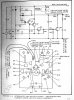
When Q5 turns off, sharply, the flow of current through L1 and Q5 is interrupted and you get a sort of 'water hammer' effect, except with electric current rather than water.
The resulting voltage pulse travels through R10, CR2, R5, and R7 to turn on Q1, and reverse the current flow, which goes through Q1. .... Can you get the value of R8?
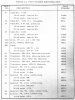
...either from the board or page 2 of the parts list. .... Also, it looks like some of the reverse current pulse goes through CR1 and R3 .... It's not really an efficient design, but apparently they got it to work.
You probably need to adjust the R7 pot. so that Q1 turns on just as Q5 turns off.
It ought to work if you can adjust R7 ... When you turn the R7 screw, take note of how many turns or quarter turns one way, and then the other that you adjust ... so you can go back to the original position if necessary.
Duffy says that Q1 and Q2 are a Darlington pair, but I'm not so sure. If Q1 turns on, then Q2 would tend to turn off. ... And Q2 current goes to a different place than Q1 current.
I would replace the 6V bulb with a 12V DC version.... probably last longer.
Also, maybe replace Q5, the power transistor. If there is evidence of heat damage, it may be defective. ... I would check it with a transistor testor ....They used to be easy to find ... not too expensive.
I don't see any speed control ... just that Q1 threshold using R7.
The new circuit and layout are not exactly the same .... but maybe close enough.