Continue to Site

Welcome to our site!

Electro Tech is an online community (with over 170,000 members) who enjoy talking about and building electronic circuits, projects and gadgets. To participate you need to register. Registration is free. Click here to register now.

  • Welcome to our site! Electro Tech is an online community (with over 170,000 members) who enjoy talking about and building electronic circuits, projects and gadgets. To participate you need to register. Registration is free. Click here to register now.

Need help! Preamp or amp circuit

Status
Not open for further replies.
In post #49, How would i connect the headphones amps outputs to the decoders INPUT. Do I connect both of its outputs or ONE ouput to the decoders INPUT.

The same gos for the speaker outputs to the input of the decoder.
The preamp output feeds the decoder. The preamp output can also feed the power amps.
The power amps outputs feed a speaker or headphones.
 
audioguru.

The obsolete part was used. cos' I had it. I couldn't find a more up to date one.
Would you know of a DTMF GENERATOR thats more up to date.

In post #59 you state in question four.

The Obsolete touch-tone generator needs an emitter resistor to ground and a coupling capacitor at its output.
The TDA2822M power amplifiers need a coupling capacitor to their volume controls if the sound source has DC on it.

Where do i connect the coupling cap to the volume controls on both of the Pots or DIRECTLY to its input. What capacitor vulue can i use.

On the output of the generator I'm not using the TIP31, I'm using the TDA2228M amp with speaker.So why do i need a emitter resistor to ground and a coupling cap at its output.

If I still need that resistor and coupling cap on the generators output, what is the resistors vulue 10ohms, 100ohm, 1k what vulue do i get. And what is the capacitors vulue 0.1mf .1mf or .001mf ...
 
audioguru

I forgot to mention.

In my decoder circuit on the output of the 74LS48 do I need to use current limiting resistors for each of its segment on the 7-segment display. I would think the current is low on the 74Ls48 output. If i do need one for each segment can i use a 220 0r 330ohm resistors.
 
Would you know of a DTMF GENERATOR thats more up to date.
I haven't seen a DTMF generator IC for about 28 years.

Where do i connect the coupling cap to the volume controls on both of the Pots?
The DTMF generator IC has DC on its output so coupling capacitors are needed to feed the volume controls.

What capacitor vulue can i use?
Calculate its value with its load resistance and the lowest frequency you want it to pass.

On the output of the generator I'm not using the TIP31, I'm using the TDA2228M amp with speaker. So why do i need a emitter resistor to ground and a coupling cap at its output?
Look at the datasheet for the DTMF generator IC to see that its emitter output needs a resistor to ground. Then its output has DC on it so a coupling capacitor must be used to block the DC but pass the AC tones to the volume control.

If I still need that resistor and coupling cap on the generators output, what is the resistors vulue 10ohms, 100ohm, 1k what vulue do i get. And what is the capacitors vulue 0.1mf .1mf or .001mf ...
The datasheet shows the value of the resistor and you simply calculate the value of the capacitor with its load (the value of the volume control) and the lowest frequency you want it to pass.

In my decoder circuit on the output of the 74LS48 do I need to use current limiting resistors for each of its segment on the 7-segment display. I would think the current is low on the 74LS48 output. If i do need one for each segment can i use a 220 0r 330ohm resistors?
I haven't used an old TTL IC for about 32 years so I had to look up the old 74LS48 that is obsolete. It has 3.3k ohm pullup resistors to directly drive transistors. Its current into a common-cathode 7-segment display is only 1mA (very dim).
 
audioguru

In post #64 question 4 your reply states?

My Question.
If I still need that resistor and coupling cap on the generators output, what is the resistors vulue 10ohms, 100ohm, 1k what vulue do i get. And what is the capacitors vulue 0.1mf .1mf or .001mf ...

audioguru reply.
The datasheet shows the value of the resistor and you simply calculate the value of the capacitor with its load (the value of the volume control) and the lowest frequency you want it to pass...

I know the load resistor for the output of the Generator i need to use...

What i need to know is? Do i take the Gen output load resistor and ADD that vulue to the vulue of the volume controls vuluepot on the power amps, then calculate for the cut-off frequency and the vulue for the coupling capacitor. Or do i just take the load resistor and just calculate for the cut-off frequency for coupling cap...
 
Last edited:
The emitter resistor at the output of the generator is 240 ohms. But its output impedance might be 24 ohms.
The volume control is 100,000 ohms.
Two in series are 100,024 ohms which is only 0.024% higher so the 24 ohms is insignificant isn't it?

Even if you use a 10k volume control the 24 ohms output impedance increases the total by only 0.24% which is also insignificant.

The 100k (or 10k) volume control is the load for the coupling capacitor and its value might be plus and minus 20%.
The value of the coupling capacitor might be plus and minus 10%.
 
I haven't seen a DTMF generator IC for about 28 years.

The only DTMF generator currently available, as a 'stand alone' IC, AFAIK, is the Holtek HT9200A/B.

Unfortunately, only the /A version is available in a DIP package, and it requires a serial interface to activate the DTMF outputs.

The /B version does allow a 4 bit parallel input, but is only available in an SMD form. There was a 14 pin DIP version, but it was discontinued some years ago. You might still find one (I recently found 500 for a recent project), and it's certainly a lot more recent than the 5087/8/9 devices mentioned in the thread.

More details here: **broken link removed**
 
It seems that the guys in 3rd-world countries have thousands of obsolete ICs.
 
audioguru.

Yes I know the emitter resistor is 240 ohms as you stated in post 64 it would be in the datasheet and needed for the generators output transistor.

The generators output impedance could be 24 ohm.

So. Your saying that by adding the 24 ohm output inpedance would be insignificant, do to its added 0.024% for the 100K and 0.24% for the 10K which would be irrelevant to the load.

So all i need to do is calculator for the cut-off freqency from the load using a capacitor to get its cut-off Fq. Can i go as low as 30Hz or stay above 50Hz or dose it matter how low or high I need to be at but staying below 70Hz.

In the generators datasheet it states in the notes 1-2 to use capacitor at 5% and resistors at 1% if i use those percentages how would this affect the out come on the circuit...

As for the holtek DTMF tone IC i do know about them and i was going to use the HT9200B but i did not want to use a MCU to control the IC, and i did not know if you can use it without a MCU, so thats why i opted to use the the 5089 standalone IC.

Thanks for suggesting the HT9200A/HT9200B ICs. I will search for the 14 dip version see if i could locate some.

As for the guys in the 3 world countries there min quantities are about 1000-10000 parts to order from them. So I would need to find some here locally.
 
As for the holtek DTMF tone IC i do know about them and i was going to use the HT9200B but i did not want to use a MCU to control the IC, and i did not know if you can use it without a MCU

Yes, you can use the HT9200B without an MCU --I do it all the time. Just use a couple of simple logic ICs -like the 74HC148 for example -- to encode 16 inputs into the 4 bit parallel words required by the data inputs on the HT9200B.

Download the ST datasheet of the 74HC148 from here: 74HC148 Datasheet pdf - 8-3 Line Priority Encoder - Fairchild Semiconductor - it includes application notes for using two devices to encode all 16 inputs
 
audioguru

Enclosed power amp

posted in #49 with 0.22mf capacitor for cut-off freqency plus coupling cap

Will this circuit work (as is) or do i need to add or delete any part to this bridge amp.

The output emitter resistor will be added is the placement of resistor correct. Please advise.
 

Attachments

  • Power Amp.PNG
    Power Amp.PNG
    29.4 KB · Views: 284
Enclosed power amp posted in #49 with 0.22mf capacitor for cut-off freqency plus coupling cap.
0.22mF is 220uF and its value is 1000 times too high. If its value is 0.22uF then when it feeds the 10k volume control the cutoff frequency is 73Hz so deep bass sounds will not be produced. It is fine for voices and touch-tones.

The output emitter resistor will be added. Is the placement of resistor correct?
The "emitter resistor" is connected to the output of the DTMF generator IC. Do you want to add a switch for other inputs to be played through this amplifier?
 
audioguru.

For the coupling capacitor I did mean 0.22uf its micofarad. right! So 73hz would be pretty good voice and touch-tones.

Is the emitter resistor placed correctly in the circuit..


For the Generator circuit its purpose is only to emitter the touch-tones through the Bridge amps speaker in post #49,as mentioned in post # 1..


For the decoders circuit its purpose is to recevie the touch-tones. with voice and radio sounds through the headphones. this is where i would need the switching for other inputs to the speaker and headphone amps posted in #49.. In this circuit the cut off freqency would need to be lower then 73Hz to get better Bass for music through the radio. correct!

For music would i need to go below 50Hz maybe at 33Hz to get good decent bass for music for the coupling capacitor. Advise!
 
Last edited:
Music frequencies go down to 20Hz. If you set the cutoff frequency of all the RC coupling circuits in your system at 20Hz then their cutoffs add and cut 20Hz to almost nothing and even cut 100Hz to a pretty low level. Then use a lower cutoff frequency.
 
So. what you are saying if i put all RC coupling circuits to 20Hz they will increase or add which will bring a higher cut-off Fq to about 100Hz total. So. I would need to lower the cut-off freqency to say for each input below 10Hz so when they add they do not go higher then 100Hz. Is this what you are stating. Please Advise.

Or if i use 20hz at each input for th RC circuit for the speaker amp as well as the headphone amp would this be Ok for good bass Freqencies for music. Advice.
 
So. what you are saying if i put all RC coupling circuits to 20Hz they will increase or add which will bring a higher cut-off Fq to about 100Hz total. So. I would need to lower the cut-off freqency to say for each input below 10Hz so when they add they do not go higher then 100Hz. Is this what you are stating?
correct.

Or if i use 20hz at each input for th RC circuit for the speaker amp as well as the headphone amp would this be Ok for good bass Freqencies for music. Advice.
I can't remember how many RC circuits there are for each amplifier. If there is more than one RC circuit then reduce the cutoff frequency so when they add then the total cutoff frequency for all of them is 20Hz.
 
audioguru.

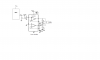
Theres only the one bridge Amp being use in the generator circuit..

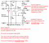
There's 3 sparate amps for the decoders circuit the PreAmp, speaker Amp and headphone Amp, but the speaker amp is used only when listening to a radio,mp3 from the speaker when SWITCHING between the speaker amp and the headphone amp..

The Preamp and headphone amp will be connected when picking up the touch tones or listening to the radio,mp3. or vioce.

I Can calculate for the RC cut-off freqency for the bridge Amp and the headphone amp, But the Preamp that you posted I have no idea how to change the input cut-off freqency below 10 hz since you post that circuit for me but i think you set it at 32Hz. in Post #7. Help. can you change it if it needs to be changed.
 
Last edited:
The bridged amplifier has only one coupling capacitor which is the output capacitor of the preamp.
I show cuoff frequency calculations of the mic preamp on my sketch.
The feedback capacitor creates a cutoff frequency too low at 3.3Hz so its 22uF capacitor could be 2.2uF.

For voices a total cutoff frequency of about 50Hz sounds natural. A total cutoff frequency of 300Hz sounds tinny like a telephone.

Then select individual cutoff frequencies for all RC circuits so that the total is about 50Hz.
 

Attachments

  • electret mic cutoffs.PNG
    electret mic cutoffs.PNG
    19.1 KB · Views: 295
audioguru.

I'm not quite understanding what needs to be calculated here. In your sketch where theres 30hz cut-off freqency on the Preamps input dose that freqency need to be lower then 30Hz Or dose this freqency stay at 30hz but adds to the capacitor on the output of the Preamp capacitor which feeds the input cut-off freqency on the Power amp and the headphone amp cut-off freqency to total to 50Hzs as you suggested...

What about the feedback cut-off freqency. How dose this freqency play into the Preamps output capacitor.
Dose the feedback capacitor need to change know matter.If i change the 22uf to 2.2uf which will give a cut-off freqency of 32.88Hz on this feedback circuit instead of 3.3Hz.. Dose this freqency change an adds to the 30Hz thats on the input of the Preamp. I'm Totally confused on this. Help!
 
Last edited:
audioguru

What I also needed to know is when i connect the Preamps output to the Headphone two inputs how do i connect to the Left and right side. Do i connect two wires from the output of the preamp and connect to the left and right sides or do i connect to one side with one wire from the preamps output... Please advise.

Also the preamps output will feed the decoders input too.Advise.
 
Last edited:
Status
Not open for further replies.

Latest threads

Back
Top