Continue to Site

Welcome to our site!

Electro Tech is an online community (with over 170,000 members) who enjoy talking about and building electronic circuits, projects and gadgets. To participate you need to register. Registration is free. Click here to register now.

  • Welcome to our site! Electro Tech is an online community (with over 170,000 members) who enjoy talking about and building electronic circuits, projects and gadgets. To participate you need to register. Registration is free. Click here to register now.

Need help! Preamp or amp circuit

Status
Not open for further replies.
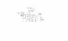
Instead of "1 over 2 pi RC" I use "0.16 over RC" instead.

Think of a cutoff frequency for your speaker then halve it because the LM386 amplifier has two RC networks. One at the input and another at the output.

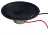
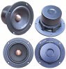
Since you are talking about a very low power amplifier then I think your speaker is tiny and cannot produce deep bass frequencies. Then your cutoff frequency can be higher.
 
Ok. Say speaker is 8 ohm PI=0.5W (size 2.5'') . So if my speaker has its lowest roll=off frequency at 320Hz, and I think it gos as high as 4000khz something like that, then half of 320hz= 160hz than i would calculate this number for the RC network for the input and the output.

The Preamp Mic has a frequency range of 20hz to 12khz or 20khz the (speaker) is not connected to the Preamp only the Mic is. BUT if I connect the input to the radio with the optional plug then I would still need a lower cut-off frequency for the radio stations. Is this correct.
If this is the case then can i have the cut-off frequency low as 70hz.
 
The amplifier can have a cutoff frequency of 20Hz if you want but your tiny speaker will not produce any bass frequencies so you might as well cutoff at 100Hz. Then the tiny spreaker will produce a little bit of low frequencies.
 
Audioguru

Will this diagram work for my project.

Enclosed is a revised diagram that i inposted in post 14 the cut-frequency now is 106hz with the input cap and 10k pot for the input.
Will output have the same cut-off frequency. or not. I tryed to calculate for the output but couldn't get the right capacitor can i use the same cap for the output or will it need to be half the vulue then the input capacitor. Any suggestions.
 

Attachments

  • Amp revised  1.PNG
    Amp revised 1.PNG
    28 KB · Views: 274
You don't need the capacitor between pin1 and pin8 of the LM386 because a gain of 200 is way too much.
The 100uF capacitor will cause a cutoff frequency of 200Hz at the output of the amplifier and the 107Hz cutoff at the input will cause the total cutoff frequency to be higher. The result will be squeaky sound and no bass. Are your speakers tiny? Why? Don't you like good sound?
 
OK . Then how much gain would I need if 200 is way to much. 20,30 50 0r 100. because a gain of 20 or 26dB might be to low. I need some adjustment if the sound is to low.

The .15uf capacitor with the 10k dose give a cut-frequency of 106.1hz. thats what it calculator out too.Did you round it out to 107hz, And yes I do like good sound?
Idid get a cut-off frequency of 99.47hz on the output by calculating with a .16uf with the 10k pot.

So what capacitor do i use on the output. for a 100hz cut-off fq as you suggested in post #23. Or like I said,would the capacitor I use be half its vulue of its input capacitor to get me the same output cut-off Fq as the input.
If i keep the .15uf for the input and the same capacitor on the output would it give me the same cut-off frequency on the output. Or would i need to take the
.15uf and divde that in half which will make the two caps .075 for the input and for the output. Because I having trouble calculating for the out put cut-off fq to match the input.

Yes my speaker are tiny( to keep the project small ) its only 2-1/4'' round speaker for the generator side for my project as posted in post #1.The LM386 will use the same speaker for sound that will come from a portable radio or from the Dtmf generator 25ft or more away from the Mic preamp. I'm not biulding a Hi Fi expensive stereo system.But I would like desent clear sound.
 
Last edited:
Enclosed photo. This is the size speaker Im using its 2 1/4'' round 8 ohms 86dB .5Ws

The reason for the size is keep the project small.

Dose it matter the size of the speaker.

It the size of a portable FM/AM radio speaker.
And some do have good sound. What would be a reasonable size to use. and i don't think the size is going to matter for a portable radio sound quality.
There is a speaker I seen at digikey 71mmX40.10mmX25mm which puts out 3W max rated 5W 8 ohms 86dB 100hz-20khz would that speaker make a big diffrence in sound quality. And have the low bass frequencies.
 

Attachments

  • 2.5'' 8 ohm speaker 0.5W.jpg
    2.5'' 8 ohm speaker 0.5W.jpg
    17 KB · Views: 602
Last edited:
It would sure help with volume, but the enclosure itself is going to play a huge part of how good the audio sounds. If you're limiting yourself to a tiny enclosure just big enough to fit the speaker all yer gonna get out of it is tiny sound. To get any kind of half decent bass or even decent mids you need a relatively large cavity with bass ports.
 
Use a 10k trimpot in series with the capacitor across pins 1 and 8 of the LM386 for adjustable gain.

Your cheap little speaker will just make squeaking sounds with no bass frequencies.

My pc amplified speakers have 3" drivers with huge magnets. The enclosures are pretty big and sealed. They produce 100Hz pefectly and 80Hz can be heard at a lower level.
 

Attachments

  • pc 3inch  speaker.jpg
    pc 3inch speaker.jpg
    33.4 KB · Views: 232
audioguru

those speakers are 3'' round diameter speaker. I would need only one speaker for the generator in post 1. not 4. and one for the 386 amp.

They are 3" diameter specker Correct!

What are the complete specs for this speaker. How much do they cost, the brand name with Mfg part number and where would i get one or two.

Also.
The circuit i post what capacitor would i need on the output if i keep the .15uf on the input to give me the 100hz output. Or do i need to put half the size of the .15uf on the input and the ouput to give me the 100hz as you suggested.

Would it work with one of those 3'' speakers you posted at 100hz output or can i still use the one i posted at 100hz output.

Ps Im not building a big ass stereo system. This is for a small unit in thats generating tones from a distance away with decent sound.
 
Your cheap tiny speaker will not have decent sound. It will not have any bass frequencies below about 300Hz. This little speaker will not sound too bad: https://www.fostexinternational.com/docs/speaker_comp/pdf/ff85k.pdf

The LM386 ampllifier will not be loud enough, use a TDA2822M amplifier IC instead.
If you use a 50k volume control then the input capacitor can be a 220nF film capacitor for a cutoff of 29Hz. Then the input will be flat down to 145Hz.
 
audioguru


Ok. If i use the circuit in figure 16 in the TDA2822M datasheet, can i use a 100k audio taper pot which I have I also have a dual audio taper type which will be need for that stereo setup. Then I don't need to purchase a pot.

Using a 100k will then give a cut-off frequency of 15.92 with a standard 10uf film or using a .05 cap would give a 31.83hz cut-off frequency on each input would this work. What would the output capacitors be for the two outputs. I would need a standard capacitor. would the 220 cap work for something lower then 145hz.

There will be the optional 8 ohm speaker between the two outputs with the headphone audio jack then the output gos to the decoder. It would be the same setup but using two channels for stereo and not one like in the LM386 setup.
 
Last edited:
Figure 16 of the TDA2822M datasheet is for a very low power stereo amplifier that you can use for headphones. You can connect an 8 ohm speaker between the outputs, connect different capacitors between pin8 and pin5 and do not feed a signal to pin6 to make a higher power bridged amplifier like shown in figure 2.
The 100k audio taper pot will be fine.
 
audioguru


So figure 2 for my application would be a better choice, and how much power dose figure 2 have then figure 16.Whats the maximum gain for this amp is it a gain of 39 or higher using figure 2 or figure 16. I want to have a variable gain so I could go from the lowest to the highest gain for maximum amplification. Or is this amp sets to a gain of 39.

What i want to do is add a plug to the inputs of the amp if i want a two channel stereo amp then with a two way switch added so i could switch from the plug or the single coming from the Mics Preaamp, but also feed the Mics Preamp output to the amps input.
Then on the output of the amp has the headphone jack and the optional speaker (like on the LM386) then the single from the output of the amp gos to the decoder.
How would i do this and which pins in figure 2 would connect to the plug for stereo and feed the Mics preamp single to the inputs of the amp. I might need to maybe use figure 1, and isn't figure 1 the same as figure 16. If this all makes sense.

Because figure 2 is mono not stereo correct!

Which circuit would give the power, stereo. and a variable gain. I stuck on the amp.
 
Last edited:
how much power does figure 2 have then figure 16?
The TDA2822M has its output power rated at a horrible 10% distortion. It is 1.1W at clipping (low distortion) into 8 ohms with a 6V supply when bridged like figure 2.
It is 0.27W per channel at clipping into 8 ohms with a 6V supply when stereo like figure 1 or figure 16.

Whats the maximum gain for this amp is it a gain of 39 or higher using figure 2 or figure 16. I want to have a variable gain so I could go from the lowest to the highest gain for maximum amplification. Or is this amp sets to a gain of 39.
The gain is 39dB which is about 95. Don't change the gain, use a volume control at each input instead.

What i want to do is add a plug to the inputs of the amp if i want a two channel stereo amp then with a two way switch added so i could switch from the plug or the single coming from the Mics Preaamp, but also feed the Mics Preamp output to the amps input.
A switch will connect stereo inputs to the volume controls of each amplifier channel or connect the mic preamp output to both volume controls for mono.

Then on the output of the amp has the headphone jack and the optional speaker (like on the LM386) then the single from the output of the amp gos to the decoder.
How would i do this and which pins in figure 2 would connect to the plug for stereo and feed the Mics preamp single to the inputs of the amp. I might need to maybe use figure 1, and isn't figure 1 the same as figure 16.
Wire the two TDA2822M ICs like figure 2 for the speakers and connect headphones through a coupling capacitor to pin1 and ground. if you can't find a headphones jack with a switch in it then use a separate switch to disconnect the speakers.

Because figure 2 is mono not stereo correct!
Yes.
One bridged amplifier for each channel.
 
Confused.

Do i use figure 2 as mono, would this give me the low disstortion, highest power output. but then this setup would not give me stereo through the headphones. Is this ture.

Or use figure 1 or 16 for stereo. Would this give me low disstortion high output power this set will give me stereo through the headphones.

So which setup will give me the best of all characteristic with this amp.
 
audioguru.

This is my understanding on the. LM386 Vs TDA2822M

The LM386 dose not have enough output power for my application in mono. correct!
One Lm386 mono chip can not be bridged for higher output power. Is this correct!
Two Lm386 can be configured as a stereo headphone amp by adding that second chip,but the output power will not increase and secondly it still wouldn't give me the power output i need.Is this Correct!

This is way you selected that i use a TDA2822M. Correct.

But if i use the TDA2822M in figure 2 in the bridge amp configuation this will give me 2-3 times the output power of (the LM386) correct! But the circuit will only give me mono sound through the headphones.Right!


Now?

Figure 1 and 16 in the TDA2822M datesheet is configured as a stereo headphone or speaker configuation. but if i use this circuit it will have low output power and it will have higher disstortion then (figure 2) But figure two will only give me MONO through the headphones and speaker. right!

So the conclusion for my application is. IF i want very low disstortion, high output power, and for a stereo configuation I would need too use Two chips of the TDA2822M in the ( figure 2 configuation) to give me what i need for a stereo configuation. Isn't this correct!

If I'm wrong. How do i configure this TDA2822M or use the TDA2822 to give me what i want and need. Because I'm more confused with this chip then the LM386. Please Advise.
 
Last edited:
The LM386 amplifier cannot be bridged. With a 6V supply its output at clipping is only 0.22W into 8 ohms.

With a 6V supply, the TDA2822M can be a stereo amplifier (2 channels) with each channel providing only 0.27W at clipping into 8 ohms.
I recommend that two TDA2822M ICs be used bridged to provide 1.1W per channel at clipping into 8 ohms. Don't you have two speakers?

Each speaker connects to two pins on a TDA2822M IC. The speakers do not connect to ground.
One earphone of headphones connects through a coupling capacitor to piin 1 of a TDA2822M and ground. The other earphone connects to the other TDA2822M through a coupling capacitor.
 
audioguru.

OK. So for me to get good decent souond through the output the speaker is to use the bridge circuit in figure 2 for 1.1W output with low disstortion.

I will only be using one speaker for the decoder, its going to be a portable unit.

And will be using only one speaker for the generators output in post #1.

I'm using only one speaker on the output for sound and use the the bridge circuit in figure 2 and if i use one tda2822m chip can the circuit still be configured for stereo or would i need the two tda2822m's chips for a stereo configuration .But I will be using only one speaker with headphone jack on the output with the suggested speaker you posted in post #31.

Do i need to use one or two TDA2822M chips in figure 2 for stereo. I'm using only one SPEAKER. Advise.
 
Last edited:
You can use one TDA2822M IC and connect it bridged to one speaker for an output of 1.1W.
Then you can use a multi-pole switch to change it to stereo for headphones.

It is easier to use a second TDA2822M and use one channel for one channel for headphones and an output coupling capacitor on the output of the bridged TDA2822M for the other channel for headphones.
 
Status
Not open for further replies.

Latest threads

Back
Top