Continue to Site

Welcome to our site!

Electro Tech is an online community (with over 170,000 members) who enjoy talking about and building electronic circuits, projects and gadgets. To participate you need to register. Registration is free. Click here to register now.

  • Welcome to our site! Electro Tech is an online community (with over 170,000 members) who enjoy talking about and building electronic circuits, projects and gadgets. To participate you need to register. Registration is free. Click here to register now.

(NEED HELP PLEASE!) 1w Amp build

Status
Not open for further replies.
Hey I'm wanting to try my hand at building a simple portable 1w practice amp and I'm still very much a beginner at reading schematics and even worse at working from them so can someone tell me if I'm going in the right direction please? Pm me if you want.
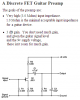
Schematics
**broken link removed**
Bread boarded
**broken link removed**
 
Last edited by a moderator:
What Help do you need?
A circuit board would be better.
What country are you in?
 
Last edited:
1. Where did you get the schematic you are using?

2. Why do you think you need Q1?

3. Why is pin 4 connected to anything? According to the datasheet, it should be left unconnected.

4. What is the signal source?

This is the datasheet I found. https://www.nxp.com/docs/en/data-sheet/TDA7052.pdf
I recommend starting with figure 3 on page 6.

Please post the datasheet you are using; it might be different.

ak
 
I agree on the odd pin 4 use.

The FET is needed as a buffer, as the amp requires a low impedance ground on the input to maintain common mode balance; 5K on the data sheet.
A guitar pickup needs a high-impedance load, preferably 500K or more.

I'd just replace the 4k7 resistor with a pot and connect the amp input to the wiper, to give it a volume control.
 
2. Why do you think you need Q1?
actually, the output of a guitar pickup is almost a line level signal to begin with. the input of the amp will get it's DC reference from the volume pot in the guitar. you also need to remove C1, as it's going to make the input float, even with the jfet. you might also try a LM386, which is essentially a 1 watt op amp. one advantage of the LM386, is since it's an op amp, you have a high input impedance on the noninverting input.
 
The schematic and photo here show a TDA7052A with a DC volume control on its pin 4, not an older TDA7052 with pin 4 not used. They are both discontinued.
The IC will get too hot and reduce its output level driving a 4 ohm load with a 9V supply. Its datasheet shows an 8 ohm speaker and a 6V supply producing 1W when clipping or 0.8W without clipping.
It will not work without C1 since its input is internally biased and without C1 then its input will be grounded with no bias.
The datasheet shows a 1M DC volume control bypassed with 1μF. With the 100k DC volume control shown then the volume will be very low.

The LM386 is a power amplifier, not an opamp. Its input impedance is only 50k ohms which is also not high enough for a geetar pickup and since it is not bridged then its output power is much less (0.3W into 4 ohms with a 9V supply) than this bridged amplifier.
 
lm386-lin-topology-small.gif

except for the internal feedback network (instead of external), it's an op amp, with a diff amp, current mirror, voltage amp, and class ab output stage. most analog power amps are basically an op amp. the LM386 has the inverting and noninverting inputs available as a normal op amp would. 50k input impedance is fine for most guitars, and that's the value used for the volume control pots in most guitars. i've used LM386 practice amps, and they work fine. it's actually very simple to use two LM386 chips for a bridged output because you do have both inputs available. like this:

lm386-bridged.png

don't use a 4 ohm speaker with the bridged circuit. a single 8 ohm speaker is pushing the envelope as well. two 8 ohm speakers in series would be preferable. each amplifier only "sees" half of the load impedance in a bridged amp. the other advantage to this configuration is that the large capacitors between the amp and speaker aren't needed.
 
Last edited:
another advantage of using an LM386, is the fact that you can make a very minimalist amplifier:

smokey-amp-schematic.gif

two caps, a connector, speaker and battery... can't get much simpler than that
 
50k input impedance is fine for most guitars, and that's the value used for the volume control pots in most guitars.
A review of the Smokey amp says that the low 50k load on the guitar pickup causes a dark muddy sound that might be balanced by the tiny output capacitor cutting low frequencies. The review says a high input impedance buffer would be a good idea. This review and other reviews say the Smokey amp is missing important parts shown on the datasheet of the LM386 therefore it is always distorted and cannot produce a clean sound.

Old vacuum tube guitar amplifiers had a 1M or higher input impedance.
Here is a guitar preamp that uses a Jfet and has a 3M input impedance and says that 1M is the minimal acceptable input impedance for a guitar device.
Here is a graph showing the guitar pickup resonates with cable capacitance and produces a peak in the upper midrange frequencies when its load impedance is high. When the load is only 50k ohms then the response is missing high frequencies like the hearing of an old person who needs a hearing aid.
 

Attachments

  • guitar preamp.PNG
    guitar preamp.PNG
    15.4 KB · Views: 224
  • Guitar pickup peak.PNG
    Guitar pickup peak.PNG
    73.1 KB · Views: 224
1. Where did you get the schematic you are using?

2. Why do you think you need Q1?

3. Why is pin 4 connected to anything? According to the datasheet, it should be left unconnected.

4. What is the signal source?

This is the datasheet I found. https://www.nxp.com/docs/en/data-sheet/TDA7052.pdf
I recommend starting with figure 3 on page 6.

Please post the datasheet you are using; it might be different.

ak
I got it from here https://www.diyguitarpedals.com.au/shop/index.php?main_page=product_info&cPath=1&products_id=84

The bill of materials says that it needs it there because the buffer was made for it.

Not a clue. I'm new to the electronics space so I don't really know how things work or why.

It'll be a guitar.

I'm not really sure what you want me to do with figure 3 on page 6.
 
A review of the Smokey amp says that the low 50k load on the guitar pickup causes a dark muddy sound that might be balanced by the tiny output capacitor cutting low frequencies. The review says a high input impedance buffer would be a good idea. This review and other reviews say the Smokey amp is missing important parts shown on the datasheet of the LM386 therefore it is always distorted and cannot produce a clean sound.

Old vacuum tube guitar amplifiers had a 1M or higher input impedance.
Here is a guitar preamp that uses a Jfet and has a 3M input impedance and says that 1M is the minimal acceptable input impedance for a guitar device.
Here is a graph showing the guitar pickup resonates with cable capacitance and produces a peak in the upper midrange frequencies when its load impedance is high. When the load is only 50k ohms then the response is missing high frequencies like the hearing of an old person who needs a hearing aid.
Maybe I'm over my head in thinking I can make some nice sounding practice guitar amps? I was just wanting to use this as a basis to make my own variation of a 1w practice amps that I could use to help me pay for a uni paper I need to finish so I can get into electrical engineering.
 
Maybe I'm over my head in thinking I can make some nice sounding practice guitar amps?
Yes, you and the guy who designed the "1W" Chime amp are over your heads because:
1) The datasheet shows an 8 ohm speaker, not 4 ohms.
2) The datasheet shows a 6V battery, not 9V.
3) The datasheet shows a 1M DC volume control bypassed with a 1uF capacitor, not just a 100k wrong value pot.
If you make the amp according to the datasheet then it will work perfectly.

The post about the Smokey Amp has disappeared. It also had many problems.
Where would I start if I wanted to learn how to make a 1w clean practice amp for guitar?
 
Years ago there were many little audio amp ICs but most are gone. Texas Instruments still make many new ones but most are in tiny packages that are soldered by a robot. Look at their list of audio power amplifier ICs on their website and download a few of their datasheets.
 
Years ago there were many little audio amp ICs but most are gone. Texas Instruments still make many new ones but most are in tiny packages that are soldered by a robot. Look at their list of audio power amplifier ICs on their website and download a few of their datasheets.
I got it going but I'm not sure what the problem was you had with it? I know I'm not the brightest person but if you explain it I might be able to understand or if you could point me in the right direction I might be able to find it out myself. Thanks for any help though.
 
I got it going but I'm not sure what the problem was you had with it?
About using the TDA7052A amplifier IC, I explained:
1) The datasheet shows an 8 ohm speaker, not 4 ohms. Therefore the IC is overloaded and might fail soon if the battery is new and the output level is high.
2) The datasheet shows a 6V battery, not 9V. Therefore the IC will get too hot and fail if the battery is new and the output level is high.
3) The datasheet shows a 1M DC volume control bypassed with a 1uF capacitor, not just a 100k wrong value pot. Therefore the volume control will not work properly.
Use the circuit shown in the datasheet instead.
Hey I was wondering if you knew where I could get a 1M DC volume control pot or what I could do to replace it with something else?
 
The DC volume control is an ordinary 1M linear potentiometer available at any electronic parts distributor. Digikey has thousands in stock of 74 different manufacturers, shapes and sizes.
I do not think it is a 1M logarithmic volume control that might be rare.
 
Status
Not open for further replies.

Latest threads

New Articles From Microcontroller Tips

Back
Top