Continue to Site

Welcome to our site!

Electro Tech is an online community (with over 170,000 members) who enjoy talking about and building electronic circuits, projects and gadgets. To participate you need to register. Registration is free. Click here to register now.

  • Welcome to our site! Electro Tech is an online community (with over 170,000 members) who enjoy talking about and building electronic circuits, projects and gadgets. To participate you need to register. Registration is free. Click here to register now.

Need help modifying a circuit

Status
Not open for further replies.

mike ryman

New Member
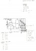
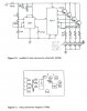
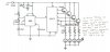
Hi, first off, I did not design this circuit. I do however need to modify it slightly. I am in the process of finishing up making my dash electronics set for a knight rider car replica. This is a schematic from the manual I have worked from. This schematic is an led sequencer. It receives 12v power, and steps down voltage to 4 pairs of led's, making them light up 1 set at a time. I need to tie into it to run 4 small led bars. each having a set of 3 led's on it, 1 per pair in the circuit. I used online resistor calculators, and tied in where I thought I would need to, but all that accomplished was all led's lighting up at once bypassing the sequenced startup. I assume the load became too much for the circuit and pulled around the timer? I made notes on my pics to help you understand what I need to do and how I tried and failed. can someone please help me?


Attachments

  • 1.jpg
    1.jpg
    242.2 KB · Views: 520
  • 2.jpg
    2.jpg
    143.3 KB · Views: 460
On the face of it, you could put a variety of loads in place of the LED pairs. You haven't said what you used, so please tell us.

Automotive electronics are notoriously difficult, mainly because it can be so noisy. It could well be that the 555 oscillator is running faster than you intended, or the 4017 is picking up noise. Do the outputs turn off if you reset the 4017 by pulling pin 15 high? I realise that you would have to disconnect pin 15 from ground for that test, and you would have to add a resistor to pull it to ground the rest of the time.

Have you tested it with the a smaller load?

A couple of points about that circuit. Firstly, the low power electronics, basically the ICs, are not at all isolated from the power parts, the transistors. I would have separated and filtered the supply to the ICs. Secondly, there is a lot of voltage drop. When all outputs are on, all the load is on the last transistor, and there 5 diode junction drops (all the diodes except the one in parallel with the 33 μF plus the base-emitter voltage of the last transistor)

That would be at least 3 volts, which is quite a lot for a 12 V system.
 
Are these white LEDs, red, ....?

Edit:
making them light up 1 set at a time
The way it's wired it should operate in 'bar mode'. The LEDs driven via pin 10 of the 4017 will be on 3/4 of the cycle time, those via pin 7 will also be on 3/4 of the time, those via pin 4 will be on 1/2 of the time and those via pin 2 will be on 1/4 of the time. I don't think that's the intended operation. IMO pin 13 should be connected to pin 1, not pin 10. This change would give a 5-step sequence changed to 4/5, 3/5, 2/5, 1/5 of the cycle time.
 
Last edited:
Thank you for replying, alec t, they are white led's on the 3 led bars I am trying to run off of the 4 led pairs. the pairs are yellow diffused, and red diffused. Diver 300, okay, to start with, the electricals are not in a car yet. I am bench testing them, so no automotive noise is present. The loads I an trying to put in are 3 led's on a small bar with a resistor. I need the 4 bars to light up along with the 4 pairs. 1 bar of 3 lights up at the same time as 1 pair of led's shown in the circuit. using a multimeter, I tested the voltage at the 4 resistors shown in the schematic. on the way into the resistors, the voltage varies. 1 has 7.6v, 4 has 9.6v, the other 2 are in between. however the output voltage is 1.94v on all 4 pairs of led's. please excuse the fact that I am not too electronically savvy. I can figure out a schematic, but have better luck with a flow chart. If you could give me a few ideas, and possibly sketch a diagram of what you think I may try would be that would help tremendously. I have tried to place the positive lead of the led bar just before the resistor in the circuit. I did this with all 4 bars, on all 4 lines. The sequential startup was bypassed. ALL led's came on on the bars and 4 pairs at once. so, I knew something was wrong hence my asking for help here. you said it appears like the 4th transistor is carrying a much higher load? could it be that my 4 led bars are causing too much draw and causing the bypass? if so, could you recommend a replacement to try? I am at a loss here. I can post a couple of pics of the boards along with the led bars if that would help
 
as for the led bars I am trying to tie in, here is a picture which shows the front and back. they are just a simple pcb I made, which ties 3 leds and a resistor together on a "bar" I need each "bar" to light up with each pair of led's shown on the schematic
 

Attachments

  • 20141025_151021.jpg
    20141025_151021.jpg
    331.7 KB · Views: 462
Mike, did you see my edit to post #3? Half of the LEDs are on most (3/4) of the time. If the cycle time is short the present sequence may look as though all LEDs are on at the same time ;).
 
Post deleted
 
alec, thank you. the pairs are sequenced to light up 1 set at a time and stay on. they dont continue to oscillate. they light up pair 1, pair 2, pair 3 pair 4 and stay lit. I am trying to tie in the 4 bars to light up 1 bar per pair and stay lit while power is on. does that make sense? I am just trying to explain as best as I can. there is about a 1 or 2 second gap before the next pair lights up all set by the variable resistor inline on the board.
 
Does the sequencing work correctly without the 4 bars?
 
How much current do the LED bars take? What colour are the three LEDs? (the voltage depends on the colour). What resistor does each one have? What are you powering the circuit from?

When all the LEDs and the LED bars are alight, can you measure all the voltages, (with the negative of the voltmeter connected to ground) and write those voltages on a copy of the circuit, and post that?

As you can probably guess from our questions, you're not doing anything stupid, and the problem isn't obvious.
 
I'd guess the extra current drawn by the bars results in transistor base current sufficient to pull down the output voltage at the 4017 pin. That may cause a malfunction of the IC (but this is supposition). Measuring the voltages as Diver300 suggests should give us a clue.
 
okay, I would rather do this 1 step at a time.... here is a list of the led infos and schematic. I measured voltages BEFORE output resistors and after. I need help figuring out what resistors to use on the 4 pairs and 4 bars due to different voltages that they require. I have tried several variations from resistor calculators and nothing has worked right yet. if you can help with that info, I will replace resistors and try to tie in where you suggest if you can get me that far. as you can see from the results, there is a pretty good variance in voltages before the resistors. the 390's in the schematic work fine for the 4 pairs, as do the 220 ohm resistors I currently have in them, so thats kind of a non issue. no voltage output change has been noted. the led bars I wish to tie in are all 3 white led's.
 

Attachments

  • led schem with info.jpg
    led schem with info.jpg
    273.4 KB · Views: 445
Last edited:
A Knight Rider circuit lights LEDs back and forth, back and forth. Your circuit goes forth but does not go back so it is like rear turn signals in a Ford Mustang car.

You posted a photo of an LED bar showing 3 white LEDs and a 22 ohm resistor. They appear to be connected in series and in series with a 22 ohm resistor. Then if powered directly from 12V their current is [12V - (3 x 3.2V)] /22 ohms= 109mA. Then if the emitter of a transistor is less than about 10V they will not light.
Each white LED must have its own series resistor calculated with its driving voltage.

Since the "after" voltages are only about 2V then I guess you have the "pairs" of LEDs connected with a red LED in parallel with a yellow LED?

The resistor values are simply calculated using Ohm's Law. You have the different voltages "into" the resistors and the "after" voltages are about 2V. 20mA should be used in the calculation.
 
As Audioguru says, with a 22 Ω resistor, the LEDs will take around 100 mA at 12 V and nothing at around 10 V. You show the output voltages to be 9.87 V, 9.12 V, 8.38V and 7.67 V, but you seem to say that all four light bars are lit. I would have expected them to be very different brightnesses, if they lit at all, with those voltages. When you took those measurements, was that with the light bars connected?

If not, could you take the readings again with them connected? It could also be useful to know the supply voltage, before and after the diode at the top left.
 
audioguru, that is ONLY for the front scanner. I am working with the voicebox led's and the dash top countdown. they do not go back and forth. the vbox led's along the outer edge light up in pairs. 2 at top, next 2 down, next 2 down, then bottom 2. at the time that the top led's light up on the vbox, the first countdown led bar lights up. second set, second bar and so on. No oscillation, no back and forth. diver 3oo, I will need to get more resistors to recreate what made it all light up at once. When they ALL lit up, the bar led's had a flicker for the 4 sequence steps but all stayed bright. As for resistor values, I have tried this a whole bunch of ways. series, parallel, tapping in before the output resistors, after them, The led bar resistor you mentioned was a 100 ohm, I used it when I was varying resistor values due to voltage variance on the main board before the output resistors. I tried several variations with resistors using this image below, but due to the varied voltage required between light bars, and pairs, I was unsure how to proceed. if I can get help figuring that part out, I can try to tap into the line and see if it works. this is going to take me a day or so. I will need to redesign my led bars to accomodate 3 led's before I can continue. If I tap into the line before the output resistors to make all led's light up in sequence, will I need to go by line individual values? as shown earlier the line 1-4 variance all evened out once output resistors were in.
 

Attachments

  • Solution 1.jpg
    Solution 1.jpg
    41 KB · Views: 396
The Circuit Wizard figures assume all LEDs are the same, with a Vf of ~2V. Your circuit use various LEDs. The white ones have a Vf of ~3.2V, so three in series will drop around 9.6V if powered correctly, passing 20mA.
 
Since the lowest drive voltage is 7.67V which will drop lower when powering the LED bar then you cannot connect three white LEDs in series and probably cannot connect two in series.
Each white LED in a bar needs to be connected separately its own current-limiting resistor.
 
I agree with AG. In theory you shouldn't be seing much/any light from some of the bars if connected as you propose. It's a mystery that you get all LEDs lit as you say.
A possible cause of lock-up of your circuit is base-emitter junction breakdown, due to reverse voltage (~10V) across the junction as a result of the transistor emitters being linked by diodes. The reverse current would be sunk by the outputs of the 4017 but could be pulling the supply down.
 
Status
Not open for further replies.

Latest threads

New Articles From Microcontroller Tips

Back
Top