Electro Tech is an online community (with over 170,000 members) who enjoy talking about and building electronic circuits, projects and gadgets. To participate you need to register. Registration is free. Click here to register now.
Welcome to our site! Electro Tech is an online community (with over 170,000 members) who enjoy talking about and building electronic circuits, projects and gadgets. To participate you need to register. Registration is free. Click here to register now.
If you want each LED to draw 20mA, then 3 in parallel will need 60mA, i.e. 3 times the current that 3 in series would draw. If excess current is the root of the problem then things won't improve .
Light dawns. I've just noticed that in your schematic the connections to 4017 pins 13 and 15 have been shown wrongly. Reset pin 15 should connect to pin 1 (count=5), clock-enable pin 13 should be grounded. As it stands there is no reset event and as soon as the 4017 count reaches 4 the clock is disabled, so all LEDs stay lit (or would do if they received enough voltage).
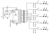
Since there are several problems with that schematic, here's a suggested alternative which should ensure enough voltage reaches the LED strings. The current-limiting resistors in series with the LEDs will need choosing to suit the actual LEDs you are using. The values shown are a rough guide only and work for the LEDs modelled in my simulation. My schematic does not show the 555 pulse generator.
The waveforms show the transistor switching voltages, demonstrating the sequencing.
Be aware that unauthorised modifications to road-vehicle lighting are illegal in many countries and may invalidate your insurance. Don't use this circuit unless you are sure it is legal and you are insured to do so.
The circuit in Alec's last post:
If the white LEDs all have a forward voltage of 3.0V instead of 3.2V and If the car alternator produces 14.4V then the white LEDs will soon burn out with a current of 54mA.
Use only two white LEDs in series then its re-calculated resistor will smooth current changes when the voltages vary.
AG's right. With little headroom between the supply voltage and the combined Vf of the LEDs, the resistor value is critical. Any small variation in Vf, resistance or supply voltage can cause a dramatic change in LED current. Which is why greater headroom (using only two white LEDs per string) or a constant-current driver is a better solution.
I redesigned my led bars, in parallel, and tied in behind the output resistors. It worked like a charm. However, the 4th transistor that is carrying a good portion of the load is getting pretty hot. Before I end up burning it out, can someone give me an idea of a possible replacement that can handle more load without the heat? it is a 2n4401
If the 4th transistor has a load of 16 x 20mA then the total current is 320mA. As an emitter follower, the 2N4401 has a minimum current gain of about 70 so its maximum base current is 320mA/70= 4.6mA. The output voltage of the CD4017 will drop to about 11V when the supply is 12V then the 2N4401 transistor has about 2V across it and its heating is 2V x 320mA= 640mW which is a little more than its maximum allowed heating rating of 625mW.
A power transistor like a TIP31 has a minimum current gain of about 40 so it will drop the voltage more from the CD4017 but it will dissipate the heat into the air better without a heatsink.
Alec's circuit is much better than the original circuit:
1) The combining of the turned on LEDs is done at the inputs of the transistors so the transistors share the load current, instead of at the outputs where one transistor powers all the LEDs.
2) The transistors are switches that have a small voltage drop instead of emitter followers that have a high voltage drop.
I'm a great fan of 4017's - they are very useful, but I think (as has been pointed out already) that the car in Knight Rider had a light which went to and fro (e.g. 1-2-3-4-3-2-1-2-3-4 etc.) rather than what you have designed (i.e. 1 - 1+2 - 1+2+3 - 1+2+3+4 etc. or similar) and you might be better off with a different counter IC e.g. one which can count up AND down. I also think that LED 2 (for instance) should be dimming as LED 3 is lighting up, as this will give the effect of "being alive" (as the car was supposed to be, or at least "intelligent") rather than "robotic". Just my opinion. I wonder if a better way would be to feed a triangle wave into an LM3914, with a couple of presets to set upper and lower limits?
Perhaps better (/alternative) advice would be to buy one on a popular online auction site! - I notice many for a couple of quid. (Quid = £1 Sterling for those that don't know).
I finished a similar project a few minutes ago:
1) Using all 10 outputs of the CD4017 I have 5 pairs of red and blue LEDs, instead of only 4 pairs. Each output has two diodes so that the LEDs turn on back and forth, 12345432123454321 etc.
2) The same transistors are emitter-followers with a high input impedance.
3) Capacitors to ground at the bases of the transistors to produce fading "comet trails".
4) I added a "power up reset" RC to pin 15 of the CD4017.
Here is the schematic:
Thanks to AudioGuru for that - out of interest I'll breadboard it tomorrow; it's a shame we seem to have lost the original poster Mark Ryman (2 years since last post). Mark let us know how you are getting on if you are out there!
In the Knight Rider circuit I posted, all capacitors are 10μF. The LED current-limiting resistors are 100 ohms for 25mA into red and blue LEDs with a 9V supply. The other resistors are 100k except 3.9k as the timing resistor on the 555.
Edit: I used a Cmos 555 then an additional 0.1uF capacitor is not needed to filter the shoot through current spike caused by an ordinary 555.
This site uses cookies to help personalise content, tailor your experience and to keep you logged in if you register.
By continuing to use this site, you are consenting to our use of cookies.

 .
. Light dawns. I've just noticed that in your schematic the connections to 4017 pins 13 and 15 have been shown wrongly. Reset pin 15 should connect to pin 1 (count=5), clock-enable pin 13 should be grounded. As it stands there is no reset event and as soon as the 4017 count reaches 4 the clock is disabled, so all LEDs stay lit (or would do if they received enough voltage).