Ok this may be easy or very complex. First up go easy on the tech stuff as i only have a basic understanding of circuit function but im capable of making most things and have no problem understanding components etc.
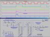
what i need is a simple square wave generator and i have found many using 555 gate etc or even 2 transistors, but what i also need is a separate secondary wave that is set at a multiple frequency of the primary, none of the circuits i found have component values and i dont know how to calculate the exact signals i require
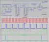
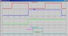
ok here are the specs: primary signal (a) wants to be about 16Hz and very short duty cycle like 2% and the secondary signal (b) needs to be exactly 24x(a)Hz with duty cycle around 30% and about 6-9v for both would be fine and the wave shape is not critical
I know the counting thing will be the killer and ideally they would be stable and accurately counted but not synchronised. i know this is asking a lot so if its too complex we can compromise and just make the secondary signal tuneable with strategically placed variable resistor and I can set it up with a 2 channel scope etc.
Ok explanation WHY!
i play with aftermarket ECU's and i often need dummy engine signals to simulate the engine running while i scope the ECU outputs and set up and zero in multi coil ignitions etc. most engines have a multi tooth trigger on the crank and a single tooth trigger on the camshaft, so this will simulate these signals, if i have a 24&1 signal i can set up the ECU for any 4, 6 or 8cyl engine
what i need is a simple square wave generator and i have found many using 555 gate etc or even 2 transistors, but what i also need is a separate secondary wave that is set at a multiple frequency of the primary, none of the circuits i found have component values and i dont know how to calculate the exact signals i require
ok here are the specs: primary signal (a) wants to be about 16Hz and very short duty cycle like 2% and the secondary signal (b) needs to be exactly 24x(a)Hz with duty cycle around 30% and about 6-9v for both would be fine and the wave shape is not critical
I know the counting thing will be the killer and ideally they would be stable and accurately counted but not synchronised. i know this is asking a lot so if its too complex we can compromise and just make the secondary signal tuneable with strategically placed variable resistor and I can set it up with a 2 channel scope etc.
Ok explanation WHY!
i play with aftermarket ECU's and i often need dummy engine signals to simulate the engine running while i scope the ECU outputs and set up and zero in multi coil ignitions etc. most engines have a multi tooth trigger on the crank and a single tooth trigger on the camshaft, so this will simulate these signals, if i have a 24&1 signal i can set up the ECU for any 4, 6 or 8cyl engine
") i know your zip file has most of the information but like i say im a bit sketchy on the technical stuff
i know your zip file has most of the information but like i say im a bit sketchy on the technical stuff