Continue to Site

Welcome to our site!

Electro Tech is an online community (with over 170,000 members) who enjoy talking about and building electronic circuits, projects and gadgets. To participate you need to register. Registration is free. Click here to register now.

  • Welcome to our site! Electro Tech is an online community (with over 170,000 members) who enjoy talking about and building electronic circuits, projects and gadgets. To participate you need to register. Registration is free. Click here to register now.

need help making a duel signal generator

Status
Not open for further replies.
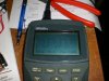
ok built it this evening and ill went together wery neat and easy, i have a primary signal but no secondary signal.

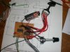
i hooked a 2 stage 6 pos rotary switch in the counter loops so i can change the count settings and a pot to alter the rpm. but i think i have the wrong connection for the of the counters

O0 i have used pin 3 zero count output?
the R i have used pin 15 reset (hooked to pole of my switch to loop back different count intervals)
input i have used pin14 clock

maybe i need to put clock enable pin 13 to earth or something??

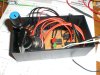
pics are attached, it will all go in the little box when its done

also why is the signal a bit of an odd shape

cheers
 

Attachments

  • CIMG0575.jpg
    CIMG0575.jpg
    99.1 KB · Views: 129
  • CIMG0579.jpg
    CIMG0579.jpg
    124.5 KB · Views: 134
  • CIMG0581.jpg
    CIMG0581.jpg
    112.2 KB · Views: 142
  • CIMG0580.jpg
    CIMG0580.jpg
    106.4 KB · Views: 160
COOL.. it all works!!

... once i enabled the clock as i thought, i bumped C2 up to 100n to give a bit bigger secondary signal and its spot on

just have to put all in the little box now
 
I showed the "enable" input to both counters tied to ground (Logic low enables).

Note that you cannot divide by zero (mathematically or practically) :D

You can divide by One, which is the same as not dividing at all.

You can divide by Ten; however, you will need to connect a pull-down resistor (100K) between the tenth input to the switch and ground. In other words, the counter will naturally divide by Ten if the Reset input is held at ground.

For more flexibility, don't you need a second "divide by" selector switch for the second counter?

The funky output waveform looks like you have a (too-small) capacitor between the logic output and the scope input. Are you running your scope AC-coupled? If so, try it DC-coupled.
 
Last edited:
not sure what my scope is set for, ive only ever used them on 'trigger' setting. the wave form really doesnt matter as long as the ecu regesters the signal, i havn't tried hooking it up to an actual ecu yet. I used a 2 pole rotary switch so it switches both of the counters at once and have just hooked them up to give me divisions of 4,6,12,24,36 and 72 as this will cover most factory triggers like ford GM and toyota etc and cover most custom setups too, enough to play with anyhow, i can add more counters or switches later if i need, aftermarket ecu's are also configorable for any division so its mostly novelty factor because its so easy... same as my 2 little LED indicators :D

can i get a larger more linier and stable frequency range? the low speed is good but once it gets up high it just sort of instantly runs away very high. for my race car with 36 divisions per 2 revolutions it will go to nearly 2.5KHz at peak rpm. need to make sure the duty cycle of the second signal doesnt go to 100% also as it approaches 70Hz. i dropped the smaller cap back in as i discovered this can happen

cheers ... i love it when things just WORK!
 
...
can i get a larger more linier and stable frequency range? the low speed is good but once it gets up high it just sort of instantly runs away very high. for my race car with 36 divisions per 2 revolutions it will go to nearly 2.5KHz at peak rpm. need to make sure the duty cycle of the second signal doesnt go to 100% also as it approaches 70Hz. i dropped the smaller cap back in as i discovered this can happen

cheers ... i love it when things just WORK!

The freq of the oscillator is proportional to 1/RC, so as you vary R, the rate of change of frequency will speed up toward one end of a pot. As you indicate, the solution is to use a toggle switch to parallel a second capacitor across the first for the lower frequencies.
 
Status
Not open for further replies.

Latest threads

Back
Top