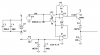
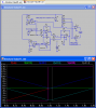
Hero, Yes, built it, ran it, tested it with DVM, Probably ought to put a scope on to see if I'm getting any of the oscillations your rightfully worried about. But it does seem to be doing exactly as spice shows it.
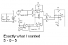
Eric, You caught me again, swap the input on U7 & U8 and you get separation instead of over lap. I will say I did draw it correctly on my schematic and as I built it, just not in spice.
Thanks,
kinarfi