Electro Tech is an online community (with over 170,000 members) who enjoy talking about and building electronic circuits, projects and gadgets. To participate you need to register. Registration is free. Click here to register now.
Welcome to our site! Electro Tech is an online community (with over 170,000 members) who enjoy talking about and building electronic circuits, projects and gadgets. To participate you need to register. Registration is free. Click here to register now.
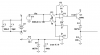
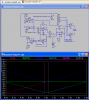
Here's what I have come up with so far and was wondering if there was a better way to covert a 0 to 10 signal to 5 to 0 to 5 signal, < 30 Hz. The absolute value circuit actually worked on a bread board, but not in Spice.
Here's what I have come up with so far and was wondering if there was a better way to covert a 0 to 10 signal to 5 to 0 to 5 signal, < 30 Hz. The absolute value circuit actually worked on a bread board, but not in Spice.
hi,
If your posted circuit is correctly drawn, it does not work.?
For example the +5Vref OPA outputs 0V.
The main output on U5 pin #1 just follows whats input on Vin.
Have you posted the wrong circuit.? EDIT:
The error in your drawing is the +5Vref circuit.
hi,
I think what he is after is making the +5V point of the 0V to +10V input signal his 0V output reference voltage, also he wants to output the absolute values of the 0V to +10V input.
So he will get +5V thru 0V thru +5V, for a 0 to +10V input.
Some answers and reasons, I have a strain gauge feeding an instrument amplifier and the output was from about 2 to 12 with a 14.4 supply and a 50% reference, power is from the alternator of a vehicle and drops to about 12 when the engine is off, so I basically have an unstable power supply to contend with. I am using an LM317 to provide a stable 10 v and need a 0 - 5 to control the out put of another controller, so I'm using a 5.00 ref for the strain gauge amp and another 5.000 ref for voltage manipulation to achieve an absolute 10 - 5 - 10 then subtract 5 for my 5 - 0 - 5 to feed the controller and flipping an h bridge with the out to NFETs which feeds PFETs with a small dead band.
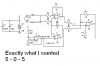
Eric was correct about having some incorrect wiring, I replace spices 5 v supply with the voltage divider as I developed the schematic and didn't run/check it. I have corrected it and included it, hope this clears up some questions about why I wanted this. If you have any suggestions, I'm listening.
Thank for the help,
Kinarfi
Actually, It's working very good. As I put 0 - 10 into it I get a very good +5 to 0 to +5 out. It's 10 to 5 to 10 after the absolute value, 5 to 0 to 5 after the "subtraction". Presently waiting for the interface to controller. It's supposed to take 0 to 5, but it's only taking 1 to 1.7 as is. Hopefully it can be reprogrammed.
It is just 2 quad op-amps and an instrument amp chip + resistrors & diodes.
Kinarfi
Hero, Yes, built it, ran it, tested it with DVM, Probably ought to put a scope on to see if I'm getting any of the oscillations your rightfully worried about. But it does seem to be doing exactly as spice shows it.
Eric, You caught me again, swap the input on U7 & U8 and you get separation instead of over lap. I will say I did draw it correctly on my schematic and as I built it, just not in spice.
Thanks,
kinarfi
This site uses cookies to help personalise content, tailor your experience and to keep you logged in if you register.
By continuing to use this site, you are consenting to our use of cookies.