Electro Tech is an online community (with over 170,000 members) who enjoy talking about and building electronic circuits, projects and gadgets. To participate you need to register. Registration is free. Click here to register now.
Welcome to our site! Electro Tech is an online community (with over 170,000 members) who enjoy talking about and building electronic circuits, projects and gadgets. To participate you need to register. Registration is free. Click here to register now.
The problem is without the Load (IR LED) its functioning.When I connect the load (IR LED) it will trigger all the time without a remote.In other words pin 4 is high when I connect the Load (IR).
The input which was used for this simulation was a 1 kHz frequency, with 100 µsec pulse width. ... Used 2N2222 instead of D400 transistor at the output. ... Used a visual LED instead of the IR version.
An interesting observation was that the C1 capacitor ... originally 0.001 µF ... appears to cause a sawtooth effect on the output current waveform of the circuit ... the current going through the output diode. The sawtooth amplitude of this waveform is about 50% of the total amplitude. This sawtooth waveform also has a higher sub-frequency, within the output pulse.
Could this particular event be related to your problem?
Changing the value of C1 to 0.1 µF appears to correct the output sawtooth deviation. The output is essentially a simple square wave ... following the input very closely.
... additional comment:
I think that the sawtooth waveform was actually observed at at pin 4 of the NE555. However, at the same time, there is an obvious abnormality in the current through the output LED. If you take an oscilloscope and probe pin 4 at a high enough resolution, you should be able to determine whether your original circuit has a similar defect.
If it works without the IR emitter is it possible you have a feedback problem where the output IR is getting back into the input receiver? You could make the IR emitter an LED to see, or cover the receiver real good. They can be very sensitive.
I have also simulated your circuit using a continuous input square signal of 38KHz at 4.8V output voltage from the simulated IR-receiver which is done using a function generator.
The output signal follows exactly the input signal as you can see by the scope screenshot.
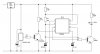
Extensive simulation shows the timer circuit runs as an astable multivibrator if the reset input voltage exceeds 1V (pretty precisely).
With the base of T2 floating this will be the case causing 1.3V at the collector which connects to the reset pin of the timer IC, hence not resetting it!
So you must force the base of T2 high enough to pull the reset pin low if there is no reception of the IR-receiver.
If you're using a series resistor with the power (+V) of the receiver just short it out and check what's going on.
Scope presentation: channel1 (yellow) -> input signal from receiver, channel2 (blue) -> signal at the base of T1, channel3 (violet) -> collector voltage of T1, channel4 (green) -> not used.
*That capacitor extreme range (0.001uF) can be a problem.
*The vero board (track board) can be another problem to add capacitance & cause to reduce the frequency.
This site uses cookies to help personalise content, tailor your experience and to keep you logged in if you register.
By continuing to use this site, you are consenting to our use of cookies.