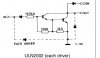
I said:The LED supply comes from a +V IGN source and the driver SINKS the LED when a positive voltage appears at the input.
the OP said:I often disconnect the truck's batter when working on the truck...
Apples and oranges. Unrelated. +V IGN only is used for the LED display, not memorizing the count.
==
But, it brings up something else: DIM You might like a lower intensity for the LEDS at night. i.e. When the headlights are on, the LEDs have a lower intensity.
==
I said:Discussion about other junk required like transient suppression, unused gate inputs HAVE to be tied to ground or +V for CMOS logic, 0.1 uf ceramic caps connect to power and ground near each IC.
the OP said:Is this shown in the schematics listed so far? or is it one of those things that you all (whom actually know what your doing) understand without having to draw it out?
It would be shown on a real schematic, but not for simulation.
Also read: https://www.google.com/url?sa=t&rct=j&q=&esrc=s&source=web&cd=1&cad=rja&uact=8&ved=0CCIQFjAA&url=https://www.littelfuse.com/~/media/electronics_technical/application_notes/varistors/littelfuse_suppression_of_transients_in_an_automotive_environment_application_note.pdf&ei=ArMPVYPUA8imNtqmgOAM&usg=AFQjCNEagIFxFNgwYh7JGwMJ1lI2sThXcw&sig2=tuMfSwjPZsqHv164k8_ZgA&bvm=bv.88528373,d.eXY
==
the OP said:For display purposes, either would be fine. I didn't realize that was option and was familiar with LEDs
7 segments displays are just LEDS and there are IC's that take a 4 bit binary/BCD number and create 0-9 and sometimes a-f. Bezels are harder to come by.
Last edited: