B Foulk
New Member
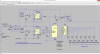
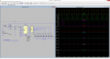
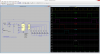
Aight fellas, while you all have provided some incredible insight, and I have followed some of it, I need to put something together using my limited capabilities. While I learn from the things you all have posted, I'd like to produce something as a "working temp model". To help you all help me, this is a schematic that shows you were I am so far. The numbers may be wrong, and this probably isn't the best model with the cleanest edges (and I have no idea about the circuitry inside the strobe unit)
But will this do as I need it to?

But will this do as I need it to?
Last edited:
")


 .
.