Continue to Site

Welcome to our site!

Electro Tech is an online community (with over 170,000 members) who enjoy talking about and building electronic circuits, projects and gadgets. To participate you need to register. Registration is free. Click here to register now.

  • Welcome to our site! Electro Tech is an online community (with over 170,000 members) who enjoy talking about and building electronic circuits, projects and gadgets. To participate you need to register. Registration is free. Click here to register now.

Multisim 74LS85 problem

Status
Not open for further replies.

tsalapatas

New Member
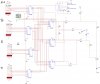
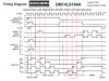
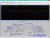
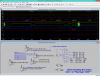
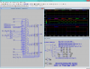
HI all i am new to this site but i am doing my thesis and i have a serious problem and however i push my brain i cant find a solution.so i am building a circuit in multisim that get the sides of triangles and sqaures and then find the are in cm.i am using as my teacherr adviced me some shift registers and comparators 74ls85.My problem is that even though the connnection are correct when i run the simulation and i connect the oscilloscope to the the tree outputs of the comparator the results are : when a>b it shows correct that voltage is going through only that the same about a<b but when the inputs from both a and b are the same the oscilloscope shows that the voltage goes through a>b and a<b and not through a=b and however i change it no voltage goes through the a=b pin,can anyone help me its driving me insane thank you looking forward to hearing from all of you
 
set up your own model for digital comparator (optimistically assuming the real thing has no bugs)
fine revise your setup (as verifying each input/control signal is exactly what it should be -- do not assume 'em being some defaults)
your input is not such that results in "undefined" output the circuit can't handle
perhaps - some random cascading example http://www.electronique-et-informatique.fr/anglais/Digit/Digit_11TS1.html
**broken link removed**
perhaps.2 - notes about some special issues http://www-classes.usc.edu/engr/ee-...g_Comparators/EE101_Cascading_comparators.pdf
revealed by "sn7485 known issues -patent" google search
. . .
 
Last edited:
Welcome to the forum, please show the whole schematic. Also, what do you mean by "find the are in cm"?
 
Yeah sorry i meant the area in centimeters. that doesnt matter what matters and is my problem is that the comparators 74ls85 when a<b it shows correct in the osciloscope the same with a>b but when a=b the osciloscope shows that volts pass through only a<b and a>b whem it shouyld pass through only the a=b output.
 

Attachments

  • ssss.jpg
    ssss.jpg
    386.5 KB · Views: 362
while i yet donno if i verify it in LT Spice ► the trivial issues in simulating logic circuits are . . . ???
  1. intial set/reset - especially Flops (exist inside 74194 also) - that may float long , also (differ I/O delays by chip if the anomalies presist)
  2. vary clock rise/fall edge **times - about sys clk - (if there are anomalous delays in advancement of the simulation - such are normal at level transitions - but if they take too long)
  3. (again in case of anomalies) -- do not feed digital inputs directly from supply rails (applies more for +Vcc than GND , but buffering both won't hurt) , but use either the alternate voltage sources or inverting buffers starting fom one that has it's input signal grounded (e.g. it's output can be fed to permanent logical High inputs ... and it's inversion or a separate double inversion to a logical Low inputs )
  4. run @ 10x and lower clock speed to verify the circuit
  5. PS! there are difference** simulating at 32768Hz and 32767.999Hz -- e.g. -- one may hang while the other manages to complete the simulation
  6. . . .
 
about the xx194
on datasheet they show inversed SHL (sould be multiply by 2) and SHR (should be divide by 2)
or then their MSB LSB are inversed -- i failed to setup a chip check -- coz you can't read out from thech spec what their brain fault or birth deficiency exactly is ...

although "multiply by -1" e.g. a sign error is the one most common , then what makes this particular case frustrating is that we have to verify the d/s against the real chip -- the options
  • they use untrivial MSB LSB notation where A is MSB
  • the bit order is trivial but there is typo on d/s e.g. pin numbers are correct but the naming A to D is reversed
  • the opposite of prev
  • the error is only on datasheet both pin numbering along with names
 

Attachments

  • 74LS194.png
    74LS194.png
    30.1 KB · Views: 262
Last edited:
about my word choice . . . i am sorry to speak so considering you're yonger . . . this is not a good example of anything especially far from academic ethics
on the other hand - the world has only got worse since 1980CE - the MSX had all crucial equippment and software integrated including on chip painter - many of these things were not present in PC - the MS paint got worse than the ® - the many features got reintroduced to PC as new decades later (and they got worse)
even now that i'm using Win8 -- there is no multitasking present as for filesystem no matter 6 cores present - the disk activity basically hangs all other tasks
. . . e.c e.c
those documents (d/s-s) are electronic - you can update them in flash all over the world in principle - no one gives a damn about end user
. . .
and that situation does not show trends to better

i know this and it does not change weather being polite or rude -- so if there is bugs around 40y -- not fixed -- i think there's a deficiency to blame

you don't know this (i assume) -- so you can't have that opinion

////////////////////////////////////////////////////////////////////////

back to desk . . . what it's worth . . .

there's some debug info at 5 minutes offset and 7 minutes offset
 
Last edited:
here's an example of anomalies (1-st specific relative control signal timing CLK , S0 , S1 :: 2-nd internal to ic)
and how to overcome such for a given setup (PS! the NAND elements in RS - Flops have different transition delays / as an alternate is setting them different by threshold levels)
--
setting true complementary descendants for S0 and S1 seems to fix the bug here
 

Attachments

  • simplifiedLogicTEST-0200.png
    simplifiedLogicTEST-0200.png
    48.6 KB · Views: 239
  • simplifiedLogicTEST-0200_Bug.png
    simplifiedLogicTEST-0200_Bug.png
    48.2 KB · Views: 231
  • smpLgcV_74x194.png
    smpLgcV_74x194.png
    45.1 KB · Views: 235
/!\ NB! Be aware data in the prev. post /!\
Primary verification = pass
Secondary -- not commited
 

Attachments

  • simplifiedLogicTEST-0200_Verif.png
    simplifiedLogicTEST-0200_Verif.png
    54.2 KB · Views: 243
thank you very much i solved it :) and now i have anotherr problem.well actually nota problem but some difficulty..so in my circuit after the comparing of the two 4 bit binary numbers i have to build it so it finds out the area using multiplication and then showing it using 7 segment display .so i researched and find out it can be done using the add and shift method but my problem is that i dont know what kind of parts to use in multisim for the bcd adder and shift and add control logic part.if you have any idea about that or any other way using a bcd adder to multiply 2 x 4bit numbers it would be a lot of help :)
 
maybe **broken link removed** -- i'm not shure that it's the chip i had in mind (the ® does apx. what i remember the MUL base-5 as !! X(-2,-1,±0,+1,+2) ?×? Y(-2,-1,±0,+1,+2) !! )
might be somewhere http://bitsavers.informatik.uni-stuttgart.de/components/ti/_dataBooks/1976_TI_The_TTL_Data_Book_2ed/ 07.pdf (just maybe ?? http://www.google.com/search?q=sn54ls261)

but building your own app specific ALU might be less complex task

. . .

something http://girdhargopalbansal.blogspot.com.ee/2013/10/combinational-multiplier.html -- it can't mean 8xAND (would have 1 output) must be arithmetic . . .
has also about ALU http://girdhargopalbansal.blogspot.com.ee/2013/10/computer-arithmetic.html

a side find **broken link removed**http://en.wikipedia.org/wiki/Curtahttp://en.wikipedia.org/wiki/History_of_computing_hardware
 
Last edited:
i just started thinking of dual (inches versus centimeters) display would require finally a lot of computations building it all hardware sound much like an overkill for sys. and energy cost . . . . . . . although it has the fastest response time . . .
. . . this is asked in a sense that what you are expected to achieve
  • is this "(don't economize) use/learn only a discrete logic" course
  • is this automation course - your own choice of setting up your apparatus - and provide system evaluation/critics at the end
  • anything else - for example : where you need to focus on some specific sub-module and the rest of the system is just illustrative as realistic device containing that module
any reason to compute in BCD when you can do binary arithmetic and later convert BIN→BCD **broken link removed**
+ the chapter 4.3 provides a backgrounds for a topic i hinted in earlier posts
 
Last edited:
i think we are kinda getting of topic :p 
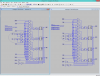
its much simpler than i made you think i want to know how to multiply 2 signals using shift register and adder, i found some examples online but just the generic logic .what i dont know is how the connection goes between the registers and the adder and what part numbers to use,i kinda understand the logic but i dont know how exactly the connection goes betyween them and count down register
 
never done such, sorry ... to get more off the topic there is an analog alternate to this (the advantage of what is the precision is somewhat set by end point ADC http://electronics.stackexchange.co...log-signal-arithmetic-faster-than-digital-one has a link to transimpedance stuff , http://www.linear.com/solutions/5633 , http://redlum.xohp.pagesperso-orange.fr/electronics/transimp.html , http://www.analog.com/media/en/training-seminars/tutorials/MT-079.pdf)

http://users.utcluj.ro/~baruch/book_ssce/SSCE-Shift-Mult.pdf -- some example - also with no practical circuitry mentioned but the lower reg.-s are likely buffered shift registers or a combination of shift + buffer the alu is binary adder the input (top) is (parallel) buffer

if i read it right and you only need to multiply from 0² to 15² e.g. 8 bit TOT input the product can be fetched from ROM and done if you presort your operands the amount of rom required is theoretically reduced to (fast guess) 16!/(2!14!)=120 excel chk. . . . = 136 . . ? . . so the formula doesnot count 0,0 to 15,15 e.g. a fix was 120+16 = 136 - i guess the required input translation circuitry does not pay off using the entire 256byte rom . . .

PS! Please ignore everything you do not need (i just splash all options here that are somehow related to this topic)
 
Last edited:
Status
Not open for further replies.

Latest threads

New Articles From Microcontroller Tips

Back
Top