Charlieplexing works fine with 7-segment displays but I don't think it would be a good solution for Erik's needs.
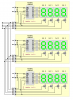
Dedicated display driver ICs would reduce I/O pin requirements but can be a bit pricey. Multiplexing is a viable solution. Perhaps a modular design? How about three seperate 4-digit modules running off a 5-pin interface with PWM brightness control? Just connect the 'SER' line on each module to a unique line (RB2, RB3, or RB4) and load the shift registers on the three modules in parallel (a bit banged 3-channel SPI bus of sorts) by retasking the column driver lines for use as 'SER' and 'CLK' lines during a short display blanking interval at the beginning of each column update interrupt cycle.
Anybody want to see software for this design?
Attached untested BoostC demo for 16F88 below. Most of the interrupt driver code just sets up the special 8 byte 'srdata' array which is used for a 3-channel SPI update of the three 74HC595 shift registers in parallel in just 24 instruction cycles at the beginning of the next interrupt.
")

