Continue to Site

Welcome to our site!

Electro Tech is an online community (with over 170,000 members) who enjoy talking about and building electronic circuits, projects and gadgets. To participate you need to register. Registration is free. Click here to register now.

  • Welcome to our site! Electro Tech is an online community (with over 170,000 members) who enjoy talking about and building electronic circuits, projects and gadgets. To participate you need to register. Registration is free. Click here to register now.

Multi earphone amp system-help

Status
Not open for further replies.

giusepped

New Member
Hello.
I am trying to build a system that amplify the signal of microphone and distribute it to a number of earphone.
The system is intende for a conference room, where the intrpreter must talk silently to a number of persons.
I bought some kit but for now they do not work.

I have one stage as pre-amp and another stage as 1W power amp.
For now I connected just 1 earphone.
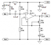
The 1W power amplifier is based on TDA7052 from Philips. Some details her**broken link removed**
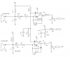
The pre-amp is based on two bipolar transistor, details here**broken link removed**(sorry for the language)

My problems
1) I don' know how to connect the microphone to the pre-amp.
in fact, I ear just intereference and noise. I connected the output of the pre-amp
to the amp. Moreover, have I to put some filter (50Hz filter) between the pre-amp and the amp?
2) How I can test the connection of the mic? I bought it in a shop, it has a jack with 3 terminals.
3) How can I be sure that when I will put more than one earphone, the signal will be strong enough? In fact

Any other suggestion will be appreciated

Giuseppe
 
What is the type of your microphone? They are all different. Dynamic, electret or crystal.

Do you know what are the three terminals on your microphone? Look on its instructions sheet.

What type of microphone is the preamp kit designed for? Attach its schematic for us to see if it has the parts to power an electret microphone.

A 50Hz filter is not needed if you connect the microphone to the preamp and connect the preamp to the power amplifier properly with shielded audio cable.

What is the impedance of the headphones?
Connecting too many will overload the power amplifier.
 
Thanks for your reply and sorry for my late answer.
I spent my night for bulding the system.

First, I have some earphones, those who you use as a speaker capsule in your ear.
I found them in a local shop, and the product label did not contain anything.
So, I googled and found that these earphones has an (real) impedence of about 150 Ohm.

So, putting 8 earphone in parallel gives about 18 Ohm, still enough for the power aplifier.
The power amplifier is based on the Philips TDA7052, and it is 1W aplifier for coil-based speaker (8 Ohm). So, ther could not be any problem for a tenth of earphones.
In fact, I tried and the sound is good at every earphone, and the IC does not heat too much.

The preamp was broken and it was based on 2 transistor (emitter follower or/and base-follower scheme). So, I built anew one based on OP AMP with band-pass filtering.
I also used shielded cable and now the sound is very good and strong.


The next problem is to add another "box". In fact, this box is for 8 people only.
I would extend the system for 16 and so on people.

My idea is to put an OPAMP -based voltage-foller at every input of every box, such that
the original output of the pre-amp is carried to every box.
I think it is a good idea, because the OP-AMP will drive the cable for interconnect the boxes and also will provide an high input impadence such that subsequent boxes are not
jeopardized. But I still did not implement the idea.
Any suggestion about it?

P.S. When I was at high school I knew all these stuff. Now I forgot almost everything.
For example, the use of shielded cable is a must in audio applications, short pins, good connection on the PCB, and yes the final insertion in the plastic box are humble but not less important things! :eek:
 
Some modern opamps oscillate at a very high frequency if the capacitance of a cable is connected directly on their output. The oscillation doesn't happen if a 100 ohm resistor is in series from the opamp's output to the cable.
 
Thank you for your speed!
What you said is good for any op-amp?
I have Tl052, LM368 and others. Should I check the datasheet or its a rule of thumbs?
So, from your short answer I stem that my idea is not bad.
Giuseppe
 
giusepped said:
Thank you for your speed!
What you said is good for any op-amp?
I have Tl052, LM368 and others. Should I check the datasheet or its a rule of thumbs?
The datasheet for the TL052 shows it oscillating with 350pf on its output. They show a series resistor stopping the oscillation even if the capacitance is much higher.

An old 741 opamp can barely reach frequencies above 9kHz so I don't think it oscillates when loaded with the capacitance of a cable.

An LM368 is not an opamp.

So, from your short answer I stem that my idea is not bad.
Giuseppe
Yes, it is good.
 
Load capacitance

Again, thank you.

The datasheet for the TL052 shows it oscillating with 350pf on its output. They show a series resistor stopping the oscillation even if the capacitance is much higher.

Ok, I saw the datasheet.
The problem is that now I don't know the capacitance of the cable. I will use
shielded cables, someone said that the capacitance of these cable is about 150pf/m.
So, If I will use 2~3 m of cable, the C~=450pF.
Which value for the resistor do you suggest? I think 100 ohm is Ok, but why not 1KOhm?
There is any formula for that?

An LM368 is not an opamp.
Sorry, I was writign by polling my memory of what I have at home...

P.S. Anyway, I googled for days by hoping to find a product similar to what I am building. Nothing came out. Indeed, this application is very useful for small group of participants in a multi-lingual conference room. Ofcourse, if one does not want a high professional wireless CDMA solution, I think this gadget can be useful. I will post the schematics if it will run!
 
I have always used a 100 ohm resistor in series at the output of an opamp to feed a shielded audio cable about 1m long. You can use 1k if you want.
 
Thank you again.
Now, I have been told to put a double power supplpier, i.e. battery and power line adapter (eg 6 V). Do you know some simple schematic in order to allow my box to accept both form of power supply. In particular, I would that the box automatically switches on the power from the adapter if it is inserted...
 
giusepped said:
I would that the box automatically switches on the power from the adapter if it is inserted...
Use a power jack with a switch built into it. You plug the adapter into the jack and the jack's switch disconnects the battery.
 
It is very difficult to find a plug adapter with a jack, unless you build one on your own.
I would use a more electornic solution. For example, put some diode...
The problem is to have a solution as compatible as possible with standard plugs...
 
giusepped said:
It is very difficult to find a plug adapter with a jack, unless you build one on your own.
An adapter jack with a built-in switch is very common.
 

Attachments

  • switched DC jack.JPG
    switched DC jack.JPG
    19.5 KB · Views: 366
A new question

Thank you audioguru, I will search it in my local store...

However, I put the schematic for the preamp I have been using.
Another question. I would use just one microphone, and not two, as in the schem of the preamp.
Can I remove the second mic and connect the signal of the first one to the middle point of C1-R7? I think no because in such way I will modify the impedences...
 

Attachments

  • kw4.png
    kw4.png
    37.4 KB · Views: 327
The preamp is a horrible design:
1) Its opamps are inverting which have a low input impedance (R1 and R3 which are only 1k ohms) that loads-down the fairly high microphone output impedance of about 3k ohms.
2) The values of many resistors are too low which makes the values of many capacitors too small.
3) C3 and C7 cut frequencies above 7kHz.
4) The microphone is called a "condenser" type by mistake when it is actually an "electret" type.
5) The IC is a dual opamp for stereo. A single opamp has different pins numbers.


Here is a much better microphone preamp for a single microphone:
 

Attachments

  • Electret mic preamp.PNG
    Electret mic preamp.PNG
    6.8 KB · Views: 640
Not to mention the voltage divider biasing the op amps was drawing more current than was necessary (it was still a negligible amount, but 100K resistors were definitely an improvement).
 
The "horrible" original preamp circuit probably used a horrible LM358 dual opamp that is noisy and has crossover distortion.
 
Since we don't know much about the load, probably should put 100 ohms in series with the output to prevent oscillation.
 
Tahnk you all for your replies.
I would insist on the fact that the desing it's not mine, I bought a kit in a local store,
because I have no time to do the PCB layout.

Anyway, the PREAMP is working pretty well. Sorry, for the quick design,
I used gschem for the first time. The OPAMPS are the two you find in the 5218.
I did not check the cutoff frequencies, I will check.
However, the mic is really a condenser with two terminal. It has a FET preamplifier built in.
At least, the local vendors said to me that it is a condenser with two terminals.
Now, while I will try to implement the circuit of audioguru, may you suggest I to share the
input of the first mic with second stage? I need two output:eek:ne for the power AMP and one for the LINE....
G
 
mneary said:
Since we don't know much about the load, probably should put 100 ohms in series with the output to prevent oscillation.

The load is the input of a power AMPLIFIER TDA7052 (Philips), connected by means of an esternal shielded cable
G
 
audioguru said:
The preamp is a horrible design:
1) Its opamps are inverting which have a low input impedance (R1 and R3 which are only

I would like to know why the invering configuraiton is a problem, because in an audio amp the phase of the signal does not care. I think the designer put the inverting configuration to prevent oscillations
G
 
Status
Not open for further replies.

Latest threads

New Articles From Microcontroller Tips

Back
Top