Continue to Site

Welcome to our site!

Electro Tech is an online community (with over 170,000 members) who enjoy talking about and building electronic circuits, projects and gadgets. To participate you need to register. Registration is free. Click here to register now.

  • Welcome to our site! Electro Tech is an online community (with over 170,000 members) who enjoy talking about and building electronic circuits, projects and gadgets. To participate you need to register. Registration is free. Click here to register now.

Multi earphone amp system-help

Status
Not open for further replies.
You don't want to feed a mic signal to the output of an opamp if it has power or if it doesn't have power. Use two preamps and a mixer circuit instead.

You are right, but now I have no much money, no much time and no much tools.
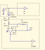
So, I thought to put a double switch in order to completely disconnect the OPAMP.
It is not a professional solution but I think it does work.
G
 
Your two preamps and a mixer can be part of the same IC package, so you really wouldn't be looking at that much of a time/cost increase.
 
Yes ,right, but I have not tool to make the pcb layout, I have only general purpose pcb boards. By the way, have you some mixer to suggest?
Regards
G
 
Final solution

So, sorry of boring everyone, I thought to do this solution, instead of using a mixer.
If I use a pre-powered mic, I will switch-off the R1 resistor. In this way, the OPAMP should
separate the two preamp. If I use a non-powered mic, I will switch on the S2 switch, and in this way the R1 will power it.
Don't you agree?
G
:confused:
 

Attachments

  • kw6.png
    kw6.png
    17.7 KB · Views: 151
I have no idea what you are doing with the opamp as a follower and switching R1.
Where is the second microphone going to connect to?
 
Ok, maybe the words are misleading.
I have ONE microphone, which is powered. It comes with battery inside a small box. SO I think it is powered. In this case I don't nedd R1, do I? Becasue, R1 serves to power the mic. The OPAMP should separate the two input of the preamps. In this way their reciprocal input impedence should not be affected.
Suppose now that the mic is not powered: I have to power it, haven'I? In this case, I use R1, and again the OPAMP separate the two preamps.
Don't you agree?
 
The purpose of R1 is to power the mic. So if your mic has a battery then tou don't use R1.

The mic preanp I showed has an input impedance of 50k ohms. You could connect up to 10 of them to your mic and they won't affect it. So the extra opamp is not needed.
 
giusepped said:
OK , but I don't know which is the input impedance of the other preamp(remember that it is a closed box to me)
G
If it works then its input impedance doesn't matter. If its input impedance is too low like the preamp you posted then the mic signal is attenuated. Simply turn up the gain of your preamp to compensate.
 
I implemented the audioguru's preamp, and an amp with tda052 from philips.
The mic is an electrect, I think. It is 2 terminal mic which need a power source.
Now the problem is that the system is to powerful! I can hear sounds very far from the mic...and also I can easily pick up the sound emitted inside the earphone capsules, located more far than 50cm, generating a larsen effect.
Actually, I did not inserted the potentiometer inside the preamp, so the gain is fixed. I just used a signal reduction at the ingress of the tda.
Any suggestion?
G
 
giusepped said:
I implemented the audioguru's preamp, and an amp with tda052 from philips.

Now the problem is that the system is to powerful! I can hear sounds very far from the mic.

Actually, I did not inserted the potentiometer inside the preamp, so the gain is fixed. I just used a signal reduction at the ingress of the tda.
Any suggestion?
The pot in the preamp circuit adjusts its amount of gain. The TDA7052 amplifier also has gain. Your signal reduction ingress circuit should be a volume control that will adjust the volume from zero.

The preamp gain is set by the value of its pot like this:
 

Attachments

  • preamp gain.PNG
    preamp gain.PNG
    16.6 KB · Views: 178
again gain

Than kou for your time, audioguru.
I will insert the pot.
However, there is a way to know which the peak-to-peak output of a typical electret mic?
More, may I ask you which eda do you use to draw schematic and to do simulations?
Regards
 
The output of a mic depends on how far away from your mouth it is and how loud you speak or sing. A low load impedance reduces its level. It is typically about 14mV p-p.

I use Microsoft Paint program to make schematics. Straight lines are made with the Shift key down and most things are copied and pasted from other schematics or datasheets.

I use SwCAD III from Analog Devices simulation program that is excellent and is free.
 
I'm a throwback, I use DPaint IV on an Amiga 1200. Schematic symbols are copied as "brushes" and stamped onto the pic, then connected with straight lines. I have text on some of the more common values already.
 
TheVictim said:
I'm a throwback, I use DPaint IV on an Amiga 1200. Schematic symbols are copied as "brushes" and stamped onto the pic, then connected with straight lines. I have text on some of the more common values already.

Amiga 1200! - modern machine! :D

I loved DPaint!.
 
Is that the DOS version or are you using an emulator?
 
Amithlon is an emulator/licensed OS & ROM package for 68K based Amiga OS's. It includes Workbench 4.0, but you can run newer or older versions on it as well. It supports Cybergraphix, but not AGA, so 1200/4000 specific apps won't work in AGA modes. That is why I'm using DPaint IV on the 1200 and Dpaint V on the Amithlon box.
 
Status
Not open for further replies.

Latest threads

New Articles From Microcontroller Tips

Back
Top