I built a transformer for my circuit and I don't think it is so good, I was wondering if someone could confirm what is happening?
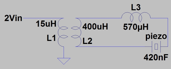
The circuit is a piezo that operates at resonance. 2V comes from an amplifier into the transformer, the piezo and inductance L3 are matched for resonance so I have around 32V across the piezo. The circuit rings/works but I have a few questions.
1) I built the transformer to have inductance of 15 and 400uH. In theory this should be a turns ratio of 1:5 with an inductance ratio of 1:25. But if I test the transformer it appears to be around 1 : 6.5, so I have 'lost' inductance and as I wound measuring inductance I have done something wrong. How important is wiring in an orderly fashion? How do I build a 'good' transformer by winding?
2) To set up resonance I have to match the piezo capacitance with L3. At the right frequency, 12KHz with a piezo cap of 420nF, in theory this is around 400uH. So L3 should be 400uH, incidentally the same as L2. But I have tested the circuit and it works better with L3 at 570uH. What is happening? Does the 'lost' inductance somehow have to be recovered for the best resonance to occur?
Szzuk.
Attachments
Last edited:
