Continue to Site

Welcome to our site!

Electro Tech is an online community (with over 170,000 members) who enjoy talking about and building electronic circuits, projects and gadgets. To participate you need to register. Registration is free. Click here to register now.

  • Welcome to our site! Electro Tech is an online community (with over 170,000 members) who enjoy talking about and building electronic circuits, projects and gadgets. To participate you need to register. Registration is free. Click here to register now.

Microphone circuit

Status
Not open for further replies.

nnb29

New Member
I'm new on this site and beginner sudent of electronics...I want to design circuit which can convert audio signals audible to man to DC supply of range 5 to 6 volt...can i use capacitor microphone???.....pls tell me about such circuit.????..also tell me range of sound signals (in dB)which is required for that circuit....
 
You need an active circuit such as an amplifier, requiring a battery. There human voice doesn't provide enough energy to give 5 to 6V at any measurable current.
 
if i use capacitive microphone (which will provide low output ) and then by connecting high gain amplifier to it will it give me required output????which amplifier shoud i use???can i connect directly it to capacitive microphone???please tell me in brief how shoud i design circuit????if any diagram as i specified above is availble on net,please tell me source if u know.....THANKS in advance...
 
You might try explaining EXACTLY what type of microphone you're talking about (no idea what you mean by 'capacitive'), and also EXACTLY what you're wanting to do with it.
 
What do you want to do with the signal, do you want to turn on a relay or something?
 
I think he is talking about using an electret microphone.
It is powered from a decoupled resistor from the positive supply and is amplified by a preamp circuit. A rectifier circuit converts the output of the preamp circuit to DC.
 
Most foreign people wrongly call an electret mic a condenser mic.
 
Microphone - Wikipedia, the free encyclopedia
read this.....the device converting sound into an electrical signal....i want to make dc source providing 5-6volt supply using sound signals and this circuit is useful for my goal.....pls answer to my queries in 3rd post of topic...

How can we?, you still haven't identified what type of microphone you want to use, or what you want to do with it - which requires completely different circuits.
 
sound energy is converted to electrical energy by capacitor microphone....capacitor microphone is nothing but similar to sound transducer ...here 1 plate of capacitor remains fixed and diaphragm acts as movable plate....diaphragm is actuated by changing pressure of sound waves striking it...hence capacitance changes and corresponding voltage drop across resistor is produced..here output is very low...so i want to obtain high dc output(5-6volt) for my instrument....(can i do it by amplifier???)
 
Last edited:
You need this:

* Microphone amplifier.
* Peak detector OR fullvawe rectifier (two opamps)

Connect those two together and tell what voltage you get out. You need to clearly define a maximum and a minimum voltage.

After that you can build an noninverting amplifier that amplifies your signal and also lift the dc-voltage to around 5 volts. That is to use a dc-voltage instead of ground (talking noninverting opamp amplifier circuit)

Why is it so important to get 5 to 6 volts out?
 
If you read the Wikipedia article you linked to, you'll discover that there are different types of microphone.

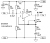
The problem is you need lots of gain and a high input impedance for an electret mic. Here's a simple circuit that will drive a small relay from an electret mic, I haven't tested it but it should work.

Tr1 is an emitter follower which has a gain of 1 and a high input impedance.

Tr2 is a common emitter amplifier which has lots of gain.

Tr3 is a precision rectifier which rejects half of the waveform. D1, R9 and R1 set the base voltage just below Tr3's turn on voltage.

C4 and R11 form a low pass filter which keeps the output switch on in-between troughs.

T4 is another common emitter amplifier which switches the relay.

R12 provides positive feedback which adds hysteresis making the circuit more stable.

R3 alters the sensitivity of the circuit.

It would be easier to build the circuit using ICs such as an op-amp and comparator but I was bored.:D
 

Attachments

  • sound activated relay.GIF
    sound activated relay.GIF
    7.8 KB · Views: 1,381
OK,thank u very much for ur help.my last question now- i hav decided to use electret microphone for my circuit......
Powering microphones

now pls look at basic circuit of electret microphone provided on above link....what will be output in that circuit????

also after scrolling down you will see circuit of Battery powered electret microphone...now will use of non inverting amplifier provide me output of 5 to 6V...???is there any modification required to get output of 5-6 Volt...
 
Last edited:
The circuit I posted includes the electret mic power supply.
 
@HERO999,thank u for ur circuit...i will really try it.....

: here in my attached image of circuit can i obtain 5-6Volt output by adjusting the potentiometer???
 

Attachments

  • chimage.png
    chimage.png
    94.3 KB · Views: 556
What do you want the circuit to do?

Do you just want a pre-amplifier or do you want a switch?

That circuit won't work because its input impedance is too low:

  • Configure the op-amp as a non-inverting amplifier which has a high input impedance.
  • Use a decent audio op-amp such as the TL072.
  • Vary the volume using a pot. AC coupled to the mic to avoid noise being generated when it is adjusted.
 
The battery needs a supply bypass capacitor and the 10k resistor feeding power to the mic and the resistors biasing the inpu of the opamp should be de-coupled from the supply like this:

The output is an AC signal 6.5V peak-to-peak into a 10k ohms load.
 

Attachments

  • Electret mic preamp.PNG
    Electret mic preamp.PNG
    5.1 KB · Views: 250
Status
Not open for further replies.

Latest threads

New Articles From Microcontroller Tips

Back
Top